![]()
Written for Crimson v2023.06.03
Introduction
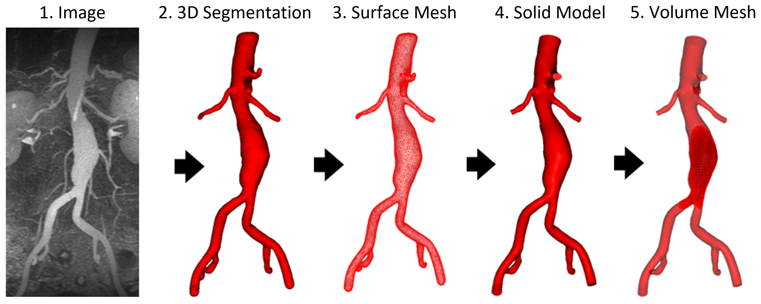
CRIMSON (Cardiovascular Integrated Modelling and Simulation) is a powerful image-based blood flow simulation environment capable of accurate and rapid segmentation of complex geometries, allowing generation of parametric models, surface and volume meshes, specification of boundary conditions and generation of the files necessary for fluid flow simulation using the CRIMSON flowsolver.
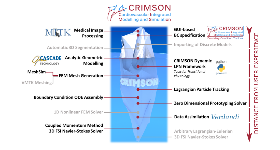
The program is built on the highly versatile MITK platform (Medical Imaging Interaction Toolkit). To the greatest degree possible, development of CRIMSON has strived to include as many of the useful inbuilt features of MITK while also providing a user-friendly, flexible, and intuitive environment for 2D and 3D vessel segmentation.
The aim of this site is to describe the main features of the Geometric Modelling environment within CRIMSON and the work flow involved in loading an image data set, creating a segmentation, mesh generation and boundary condition specification. As such this site will not describe in detail the full capabilities of the MITK platform. For further information about these features MITK documentation should be consulted.
The Big Picture
The CRIMSON flowsolver allows for Finite Element simulation. The CRIMSON GUI facilitates simulation and analysis with two main components:
- Presprocessing with geometric modelling and FEM preperation
- Postprocessing with results analyis and mesh adaptation
The CRIMSON GUI enables users to easily set up complex fluid models for massively parallel simulations. Some of the capabilities include modeling transitional hemodynamics, automatic parameter estimation (Kalman-filter), and fluid-structure interaction (linearized and large deformations).
The 2D Segmentation Approach
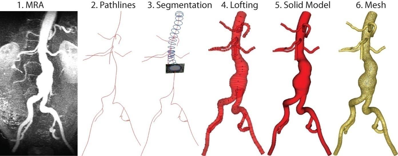
CRIMSON uses 2D-based geometric modeling instead of 3D-based volumetric modeling. In 2D-based modeling, image datasets are imported, pathlines are defined, contours are determined and then lofted to form a single vessel. Individuals can then be blended to form arterial trees.
The direct3D method requires much less user interaction, however, this leads to limitations when reconstructing complex geometries. It also results in an STL file that is then converted to a 2D or 3D mesh, this can result in poor quality meshes and limits the resolution. The 2D-based modeling results in an infinitely smooth surface defined by NURBS curves that can be meshed to any resolution.
The segmentation approach used in CRIMSON is inspired by the method put forward by (Wang, Dutton, & Taylor, 1999). This involves the following multistep approach:
-
Define Path lines
The path lines approximate the centre line of each vessel of interest. Each vessel branch generally has its own path line. This being said, if the vasculature of interest includes a bifurcation or trifurcation, for example the iliac bifurcation in the aorta, a path should extend from the parent vessel (i.e. the aorta) down one of the branching vessels (i.e. one of the iliac arteries).
The path is defined by specifying a number of points in the centre of the vessel of interest and a spline is interpolated between these points. These concepts will be clarified further in Section 4.2.
-
Define 2D Vessel Contours
Creation of the vessel path allows for "reslicing" of the image data. The reslice plane displays the image data on the plane perpendicular to each point of the vessel path. As the vessel path roughly approximates the vessel centreline, the reslice plane provides a reasonable cross-section of the vessel wall. Contours describing the boundary of the vessel wall and are created on the reslice plane at a number of locations along the vessel path.
-
Lofting
CRIMSON uses the (2D) contours to generate an analytical surface representation of the vessels by creating lofted B-spline surfaces between contours.
-
Blending and Union Operations
The final step to creating a 3D CAD representation of the patient's blood vessels is to perform a Boolean union operation, merging the B-spline representations of the different branches into a single 3D CAD model. Sharp edges between any intersecting branches can be removed via a blending operation whereby a fillet of a given radius is introduced at each intersection. These four operations are described in detail in the following section.