Theory
The baseline framework for this simulation was tracking interface migration of the SubPC surface, as the molecules undergo a vapor-solid phase transition. Due to the high jet temperatures (300C+) and velocities (200 m/s), the molecules are expected to have high kinetic energy and thus be quite mobile on the surface shortly after deposition. Thus, surface diffusion was also incorporated in the model. Lastly, besides surface energy and free energy of phase transformation, the influence of elastic stress on interface migration was also considered. We rationalized the existence of an elastic stress field as the result of a temperature gradient across the film (due to the different temperatures of the vapor jet and substrate), which caused the hotter surface to expand relative to the underlying material.
Computational Framework
The weak statement for concurrent interface migration and surface diffusion is:

J and I are vectors associated with diffusion on the surface, with
M as a parameter for mobility of molecules on the surface. δrn and
δvn relate to interface motion in the normal direction, and L is a parameter
for the corresponding interface mobility. Integrating over the entire surface gives the change in free energy
δGduring that time step. The free energy can also be related to the forces acting on the nodes by
![]() . With contributions from surface energy,
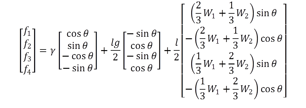
free energy of phase transformation, and elastic stress, the local force matrix on each element becomes:
. With contributions from surface energy,
free energy of phase transformation, and elastic stress, the local force matrix on each element becomes:


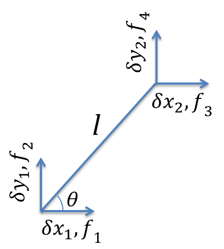
f1 and f2 correspond to the x- and y- components of the force acting on the first node of the element; likewise, f3 and f4 are the components of the force on the second node of the element. θ is defined as the angle the element makes to the x-axis of our coordinate system (so a horizontal element has θ = 0).
The parameter for elastic energy W was approximated as:
![]() which effectively places the maximum stress
at the lowest portions of the film surface.
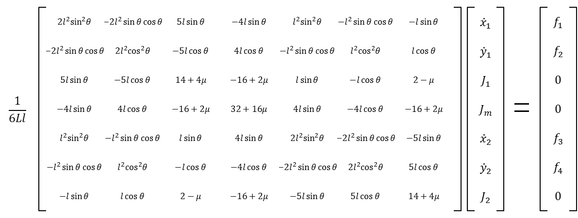
Converting normal interface motion into Cartesian coordinates, forces and nodal velocities can be related by
an H matrix as follows:
which effectively places the maximum stress
at the lowest portions of the film surface.
Converting normal interface motion into Cartesian coordinates, forces and nodal velocities can be related by
an H matrix as follows:

where µ = Ll 2 / 5M .
After assembling the local H and f matrices into the corresponding global matrices, the nodal velocities and fluxes (contained in matrix q) could be calculated from: q = H -1 f, which are used to update the nodal positions for each successive time step.
Additional Model Details
Boundary conditions were applied by adding very large terms to certain elements of the global H matrix, such that the first and last nodes of the simulated surface were fixed along the x- direction and had zero flux from surface diffusion. To prevent instabilities caused by anomolous, non-physical behavior, with each iteration, excessively high nodal velocities were re-scaled to more reasonable values, and nodes that were displaced beyond the initial x-bounds or below y = 0 (corresponding to the substrate) were deleted.
As the simulated interface evolves, some elements grow and some shrink, which eventually can lead to instabilities. In order to keep the number and relative sizes of the elements more or less constant, code was implemented to compare individual element sizes to the average at the beginning of each iteration. Overly large elements were split into two, with a new node added at the midpoint. Elements that were too small were eliminated, with their two nodes merged into a single node at the midpoint. After this procedure, the element sizes and H and f matrices were recalculated.