|
Basic Theory and Weak Statement
The following is an analysis outlines the method utilized in our simulation. The core of the analysis focuses on the solution for the weak statement of the free energy,
Following the notes from the ME 574 Nano/Micro Structure Evolution class, the equations for a segment of the code were used to solve our project. This example, shown below, contains 3 elements and 4 nodes.
Figure 1. Sample 3 element (4 node) system.
The change in normal displacement for a given node is calculated using,

This can be reduced to the following set of statements:

The normal velocity of the associated node is calculated using,
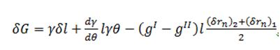
Lastly, the free energy governing the weak statement is derived as follows,
 , where quantities are indicated in the figure below. , where quantities are indicated in the figure below.
Figure 2. Free energy considerations and associated quintiles.
For purposes of solving numerical simulations the change in the free energy is redefined as
 ,where the nodal forces are shown in figure 3. ,where the nodal forces are shown in figure 3.
Figure 3. Nodal force vectors for a single element.
The theory above is used for purposes of numerical calculations. This is used to calculate the global H matrix and F vector, which in turn are used to calculate the nodal velocities and update the model geometry.
The force vector for a single element is described below,
The following local matrix, relating the velocity of nodes to the exerted forces for a single element, is defined as
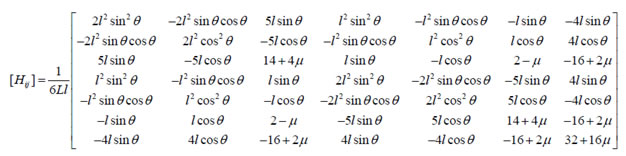
Local H matrices are assembled into a global matrix used in conjunction with the global F vector to obtain all nodal velocities. The nodal velocities are then used to increment the displacement of their specific nodes, updating the model geometry. The updated geometry is used to recalculate the global H matrix and F vector and obtain the final answer using an iterative method.
|