

The interesting feature being that exactly half of the capacitance we would normally use with a quarter wave gets used on each inductor, and this is the correct solution.
The four L.C. system fits our rope model where tension for ropes with different mass joined at the rope anti-node (inductors voltage node) can be adjusted independently. (Albeit in real life building such a rope system would be an engineering challenge.)
Correspondence predicts that the capacitors to free space are very much like "springs" with different k values that can more or less be stuck together. Field intensities diminish with distance, so the analogy has restrictions based on proximity. When two coils are far apart they react against there own capacitors as well as their neighbors, so it is very much like a mix of "springs". Capacitors in close proximity allow significant energy transfer between two coils.
Varying wave amplitudes (voltages) sort themselves out reasonably well through free space, but again proximity makes a big difference in how flux gets distributed. We can arrange a pseudo single point where roughly half the effective spark goes to the adjacent coil and the other half of the effective spark meanders about like a quarter wave. We can also operate just one coil alone with a single breakout, it looks just like a quarter wave.
As a test we also tried using capacitors for each top end such that each had the quarter wave equivalent capacitance, and as we had predicted with wave models, the distinct forms of wire length resonance/energy transfer and L.C resonance/energy storage/ transfer, were in complete conflict, causing rather severe destructive interference.
We observed that the smallest of the top end capacitors was rather leaky and always sprayed some of its arc about, indicating that the radius of curvature was a bit too small. It is also possible that the mismatch of amplitudes caused some of the flux from the smallest end to react against its own dipole.
We cheaped out on the primary (copper tube is expensive) and we got mild flashover from being horribly over coupled. (We also used the 31 gauge wire to save money.) We never meant for this coil to be a good coil. It was meant for a rough test of theory to see if the scheme works, then to get dismantled (no room for it!). We still have one last experiment to finish and post before summer ends, so we are skimping on the analysis for this experiment. If we don't get our last experiment posted by summer's end it will probably have to wait until next summer.
Pseudo single point power transmission worked out very well between the shortest pairs of inductors (with the large inductance). It does look like an effective way to get pseudo single point is by using a matched pair where each of the pairs has a long and a stubby inductor. The large radius of curvature found on the long inductors suppresses any spark and it appears to conserve energy. The alternative would be to make both inductors long and have a large radius for both top ends.
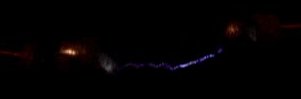
It's hard to tell from this picture, but this is between the two shortest pair of inductors for a pseudo single point transmission. The interesting thing (but not really too surprising) is that the sparks do not meet exactly centered between the two spheres. Also the sparks have different color and intensity from side to side with the brighter side being the driven side. This is real fun to see "up close" (5 feet away), pictures just don't do justice. (It also begs the question of how exactly Kirchoff's laws get satisfied.)
The following is included only for reproducibility of results, you would not want to build any keeper coil with such tiny wires and absurd proportions. It is surprising how well it all worked considering the high resistive loss, it must be the low frequency saving the day.
All figures except for lengths and radius were calculated. (and the devices worked exactly as calculated, without any further tuning!).
Oh yeah, almost forgot, we used P.V.C. for the inductor cores and spray adhesive on aluminum foil to cover the styrofoam (burnished with a coffee mug).
(L1 .08290 H, r = 2.26 inch h = 17.75 inch) C1 init. = 20.87 pf   C1f   6.62 pf N1 (1695)
(L2 .06385 H, r = 1.76 inch h = 22.53 inch) C2 init. = 27.10 pf   C2f   9.45 pf N2 (2152)
(L3 .04420 H, r = 1.20 inch h = 33.56 inch) C3 init. = 39.37 pf   C3f  14.23 pf N3 (3205)
(L4 .03703 H, r = 0.96 inch h = 43.94 inch) C4 init. = 46.76 pf   C4f  16.68 pf N4 (4196)
C1,C2,C3,C4 adjusted for Medhurst before splitting value.
cm1 = 7.64 pf, cm2 = 8.2 pf, cm3 = 10.66 pf, cm4 = 13.41pf
Example: (C1 initial c medhurst 1) / 2 = C1final Pico farad
( 20.87 7.64) / 2 = 6.62 Pico farad final (for the top end capacitance)