|
|
Saskia "crunch-daddy" Dwarshuis. A rare photo where daddy-pops, for the moment, seems to have the upper hand. |
By Lawrence Morris and Jared Dwarshuis
March, 2010
|
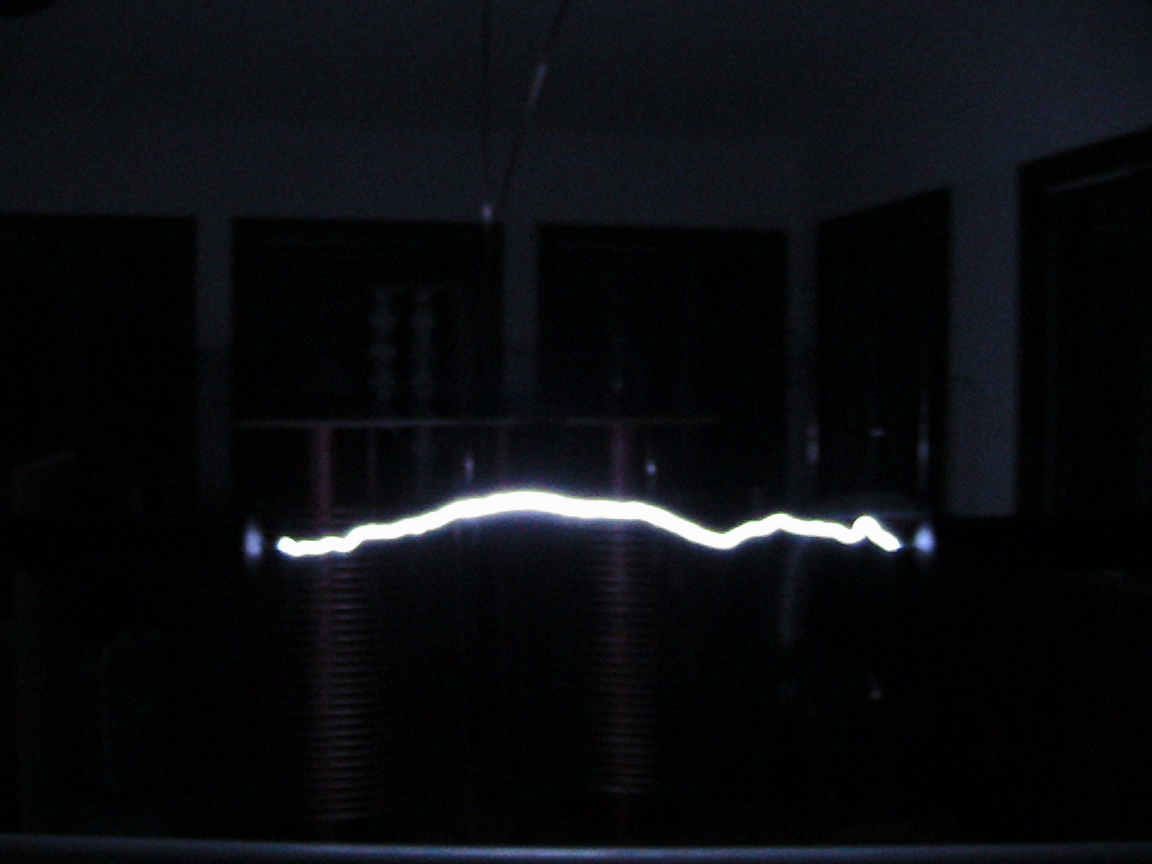
Click here to watch a video of the coil in operation |
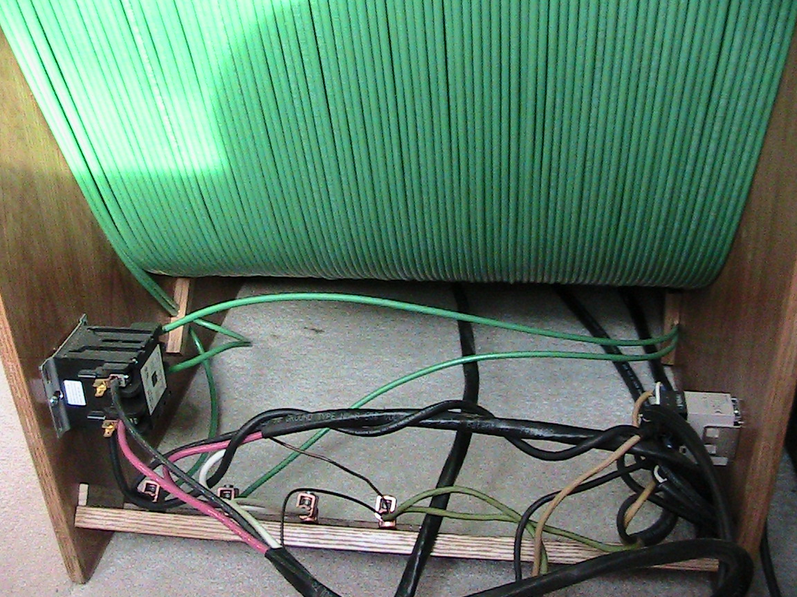
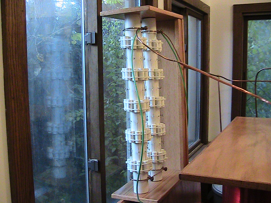
| We will start with the ballast coil. This is made with two 500 foot lengths of insulated #6AWG stranded wire laid side by side. The ballast is wired in an unconventional manner. If we call the ends of the wires on the left side of the ballast A initial and B initial and the wires on right side of the ballast A final and B final, we would say that A Initial and B final go to the wall outlet and A final and B initial go to the low voltage side of the utility transformer. All of the current travels in the same direction around this ballast. |
|
|
Our ballast is very efficient. During extended runs on a hot summer day it climbed only fifteen degrees Fahrenheit before stabilizing. We gave the ballast sufficient surface area so that no cooling fan was required. A peek inside the ballast shows nothing but air. |
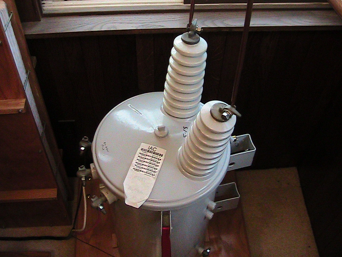
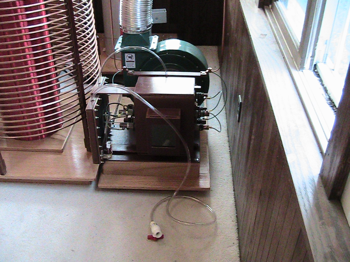
| Our utility transformer is a 10 KVA unit operating at 14,400 volts. We put this unit on industrial casters so we could move it around without breaking our backs. |
|
|
For our tank capacitor we used a total of (90) CDE-940 series 3000 volt 0.1uf capacitors wired in series/parallel for a total capacitance of 0.09uf at 30,000 volts We originally used Maxwell capacitors but found no noticeable difference in performance when we changed to the 940 series capacitors. We are fully aware that many coilers use the 942 series. |
|
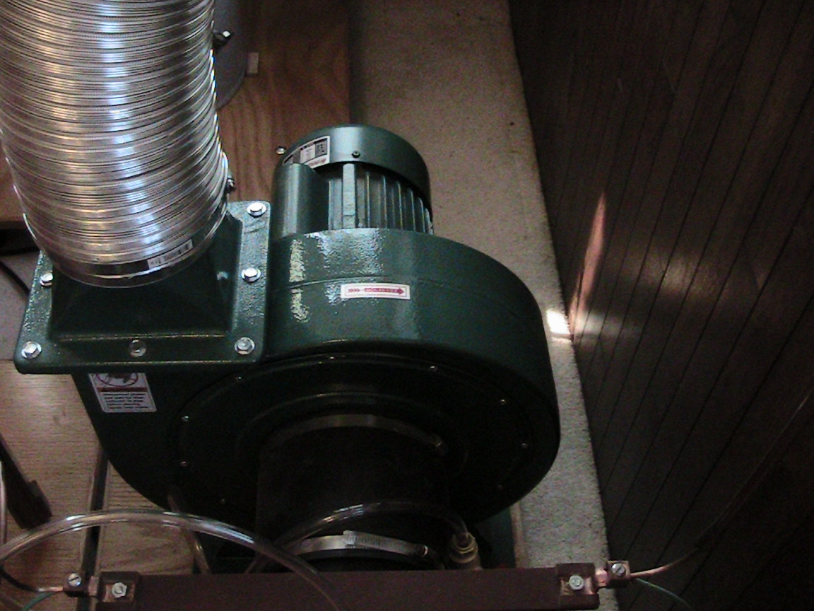
The blower is from an industrial dust collector. It is a two horse power model rated at 1550 cubic feet per minute. A rather large flow of air is required to remove ionized gas, heat and conductive deposits. |
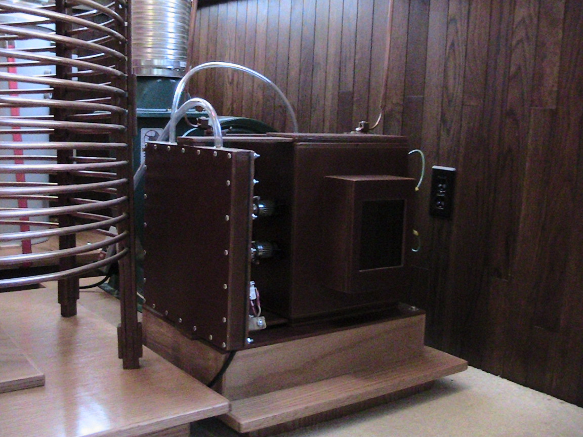
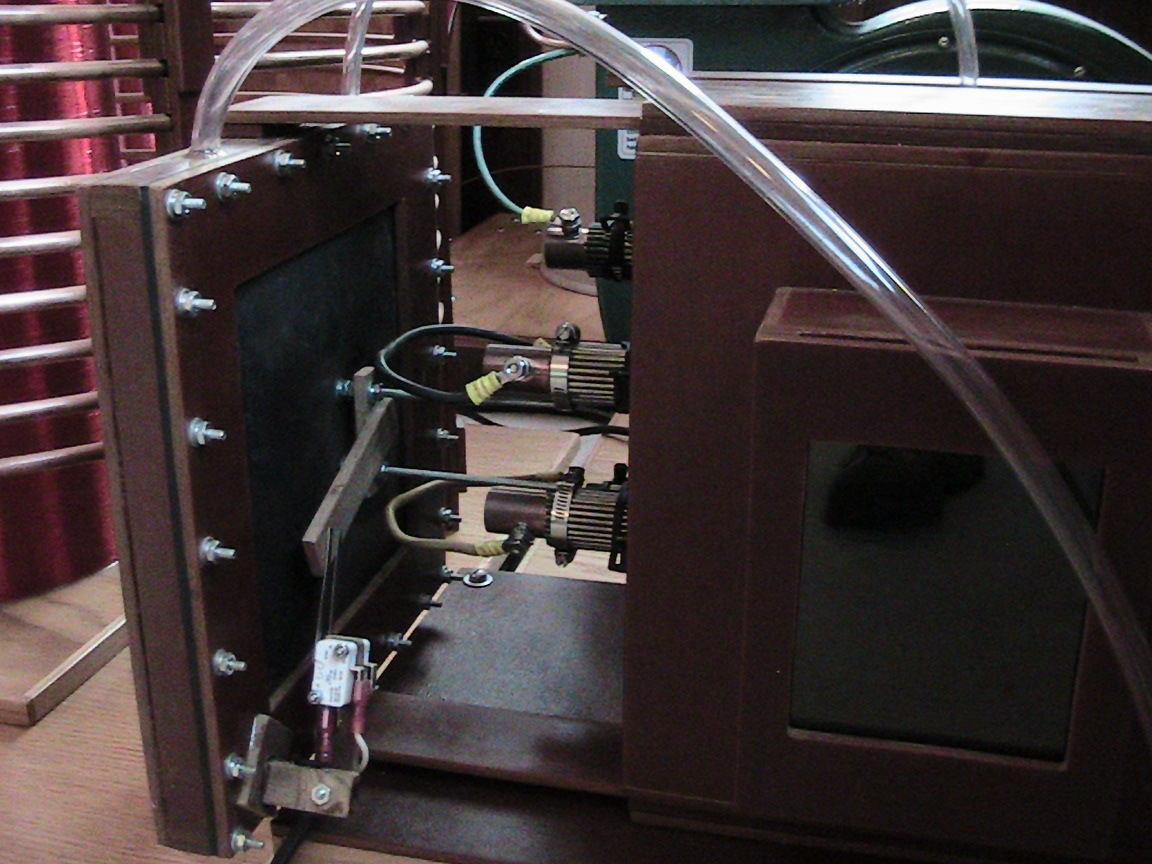
| The spark box is made of 1/4 inch grade CE Garolite and is held together with epoxy. |
|
|
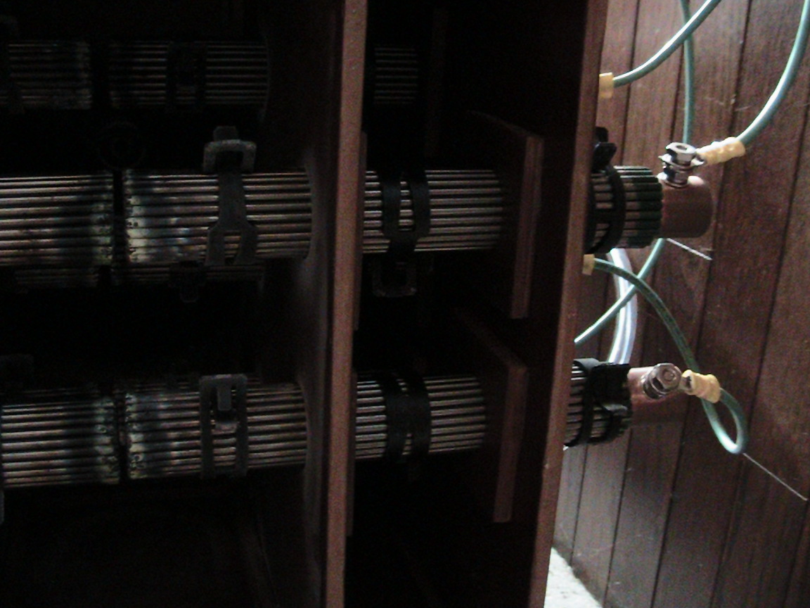
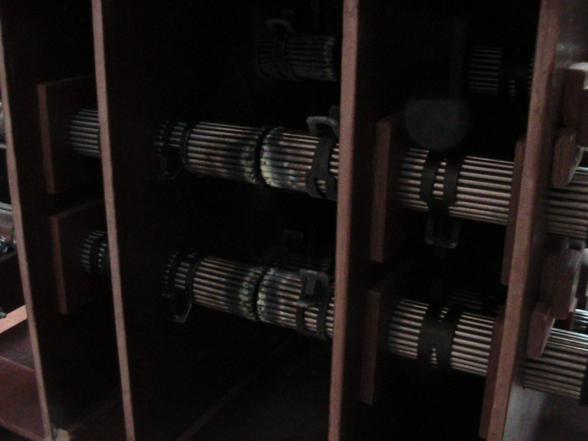
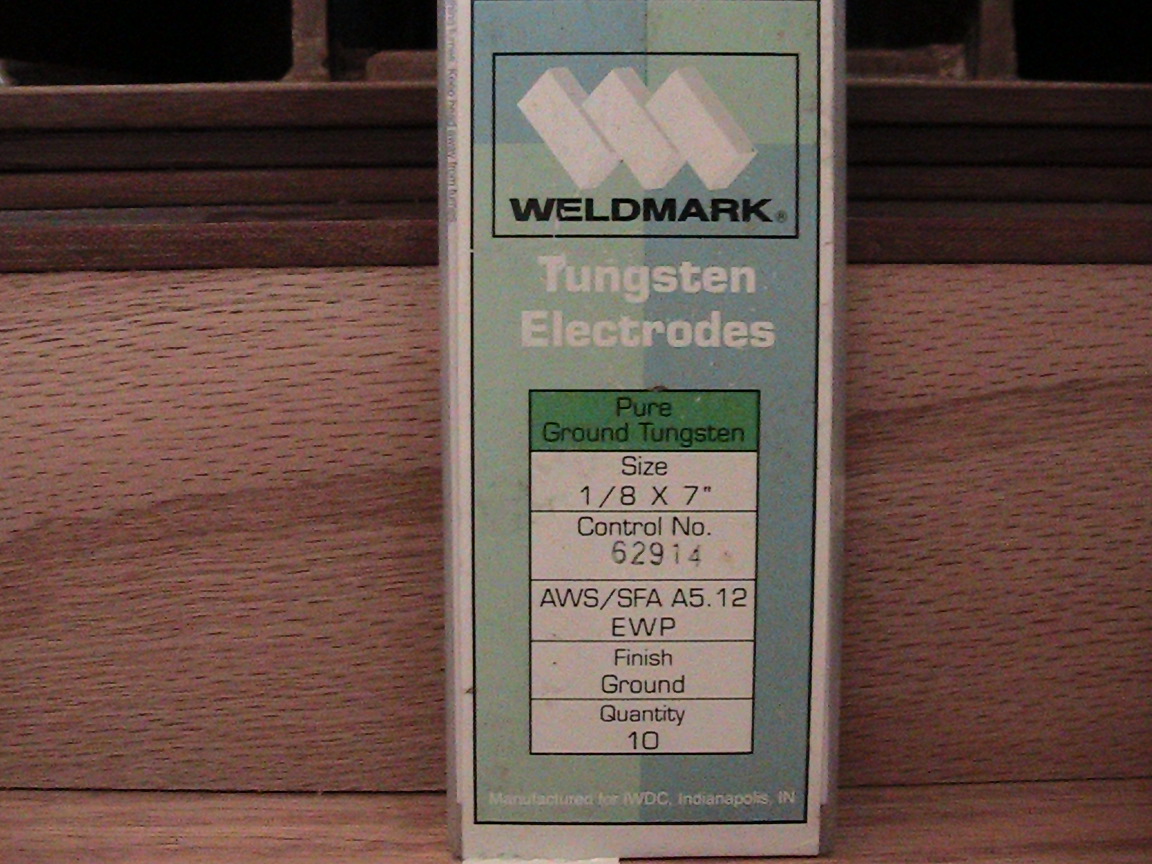
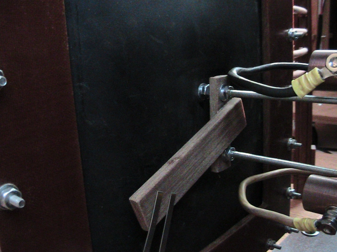
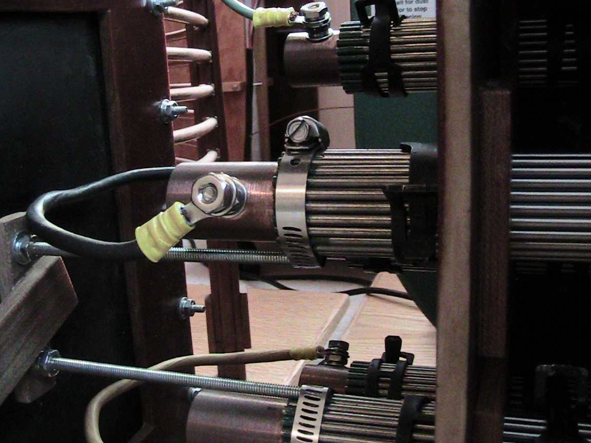
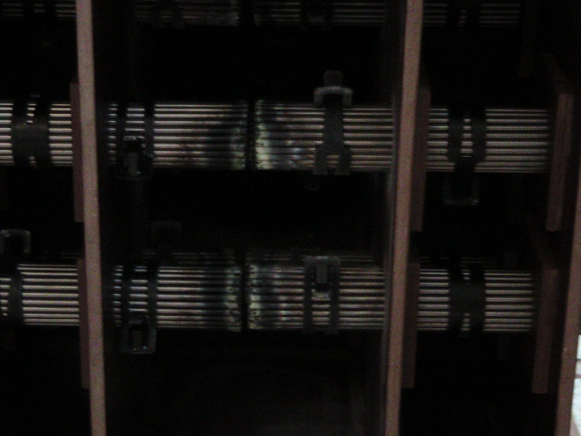
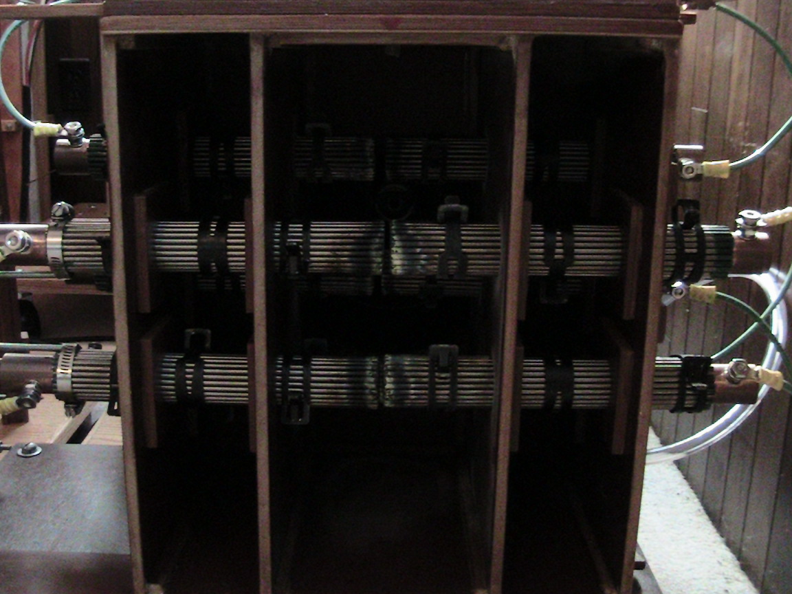
Each electrode has a total of (25) 1/8th inch pure tungsten welding rods, normally used for tungsten-inert-gas (TIG) welding. |
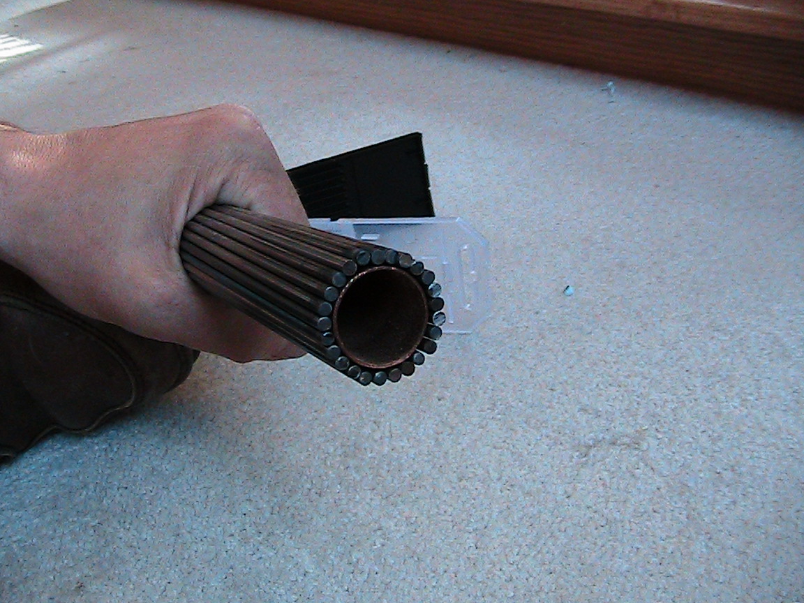
| The welding rods are wrapped around a 3/4 inch copper tube. The copper tube stops about 1/2 inch shy of the hot end. The rods are held around the copper tube with three heavy duty hose clamps per electrode. |
|
|
Two sets of electrodes on one side of the box are retracted to a hard stop by a vacuum diaphragm (made with 1/8th inch neoprene, 50A durometer). |
|
|
| A vacuum leak is introduced with a valve to set the rate at which retraction occurs, and the vacuum is, of course, provided by the blower. |
|
|
Tungsten wear is negligible with our system. The tungsten rods never get past being warm to the touch, except very near the end with the sparks. |
|
|
|
|
|
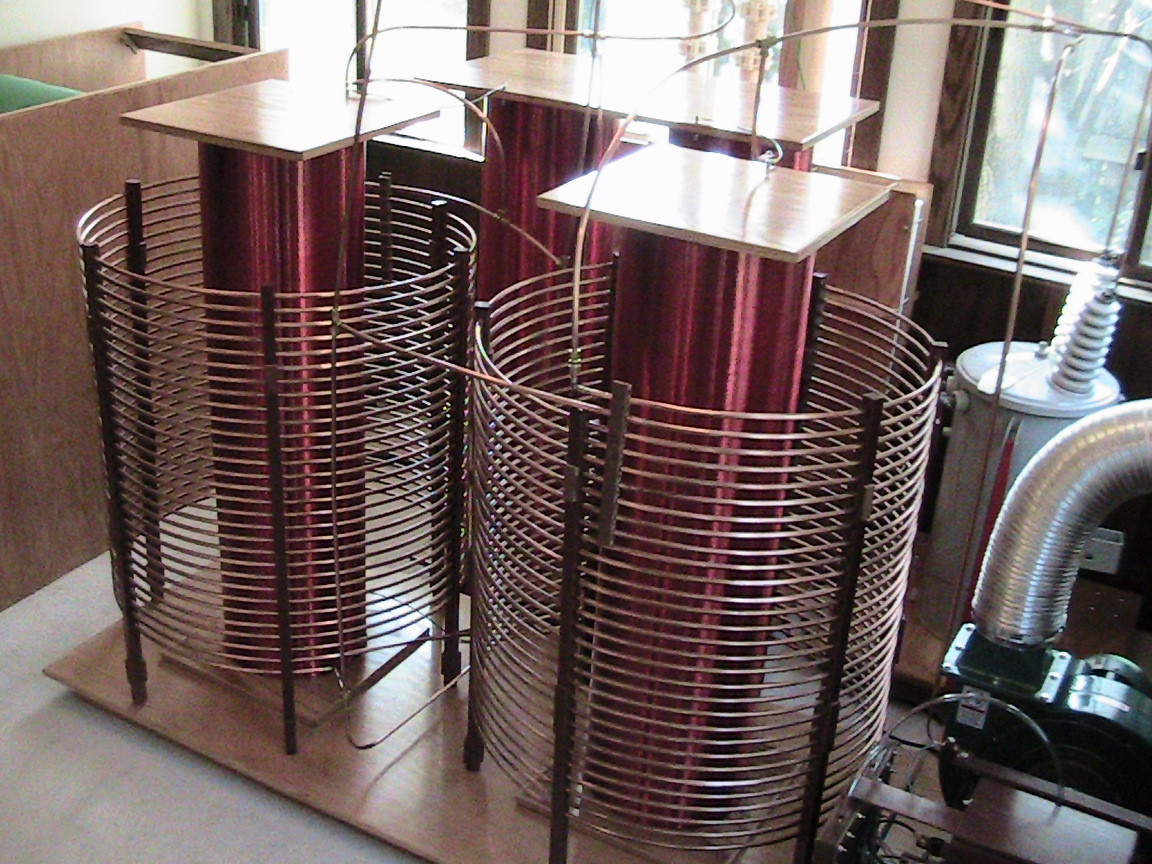
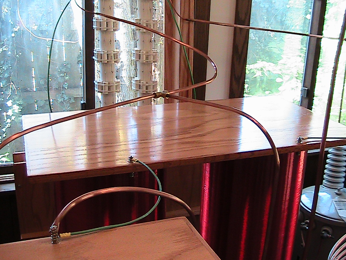
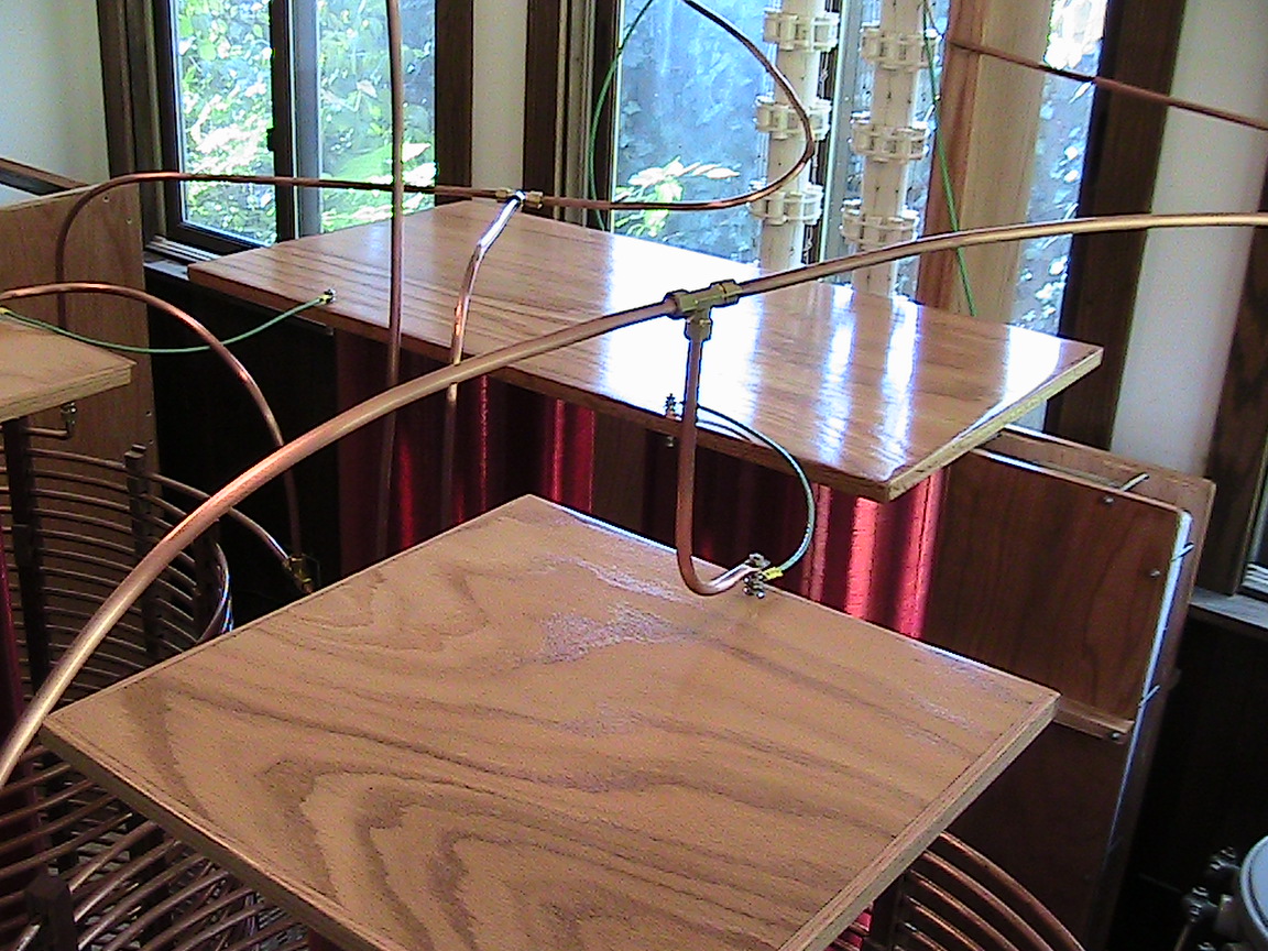
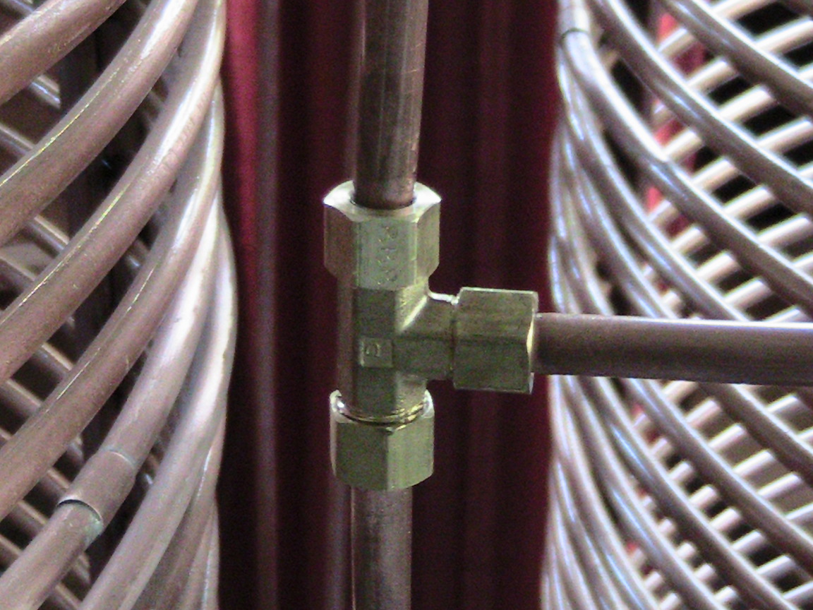
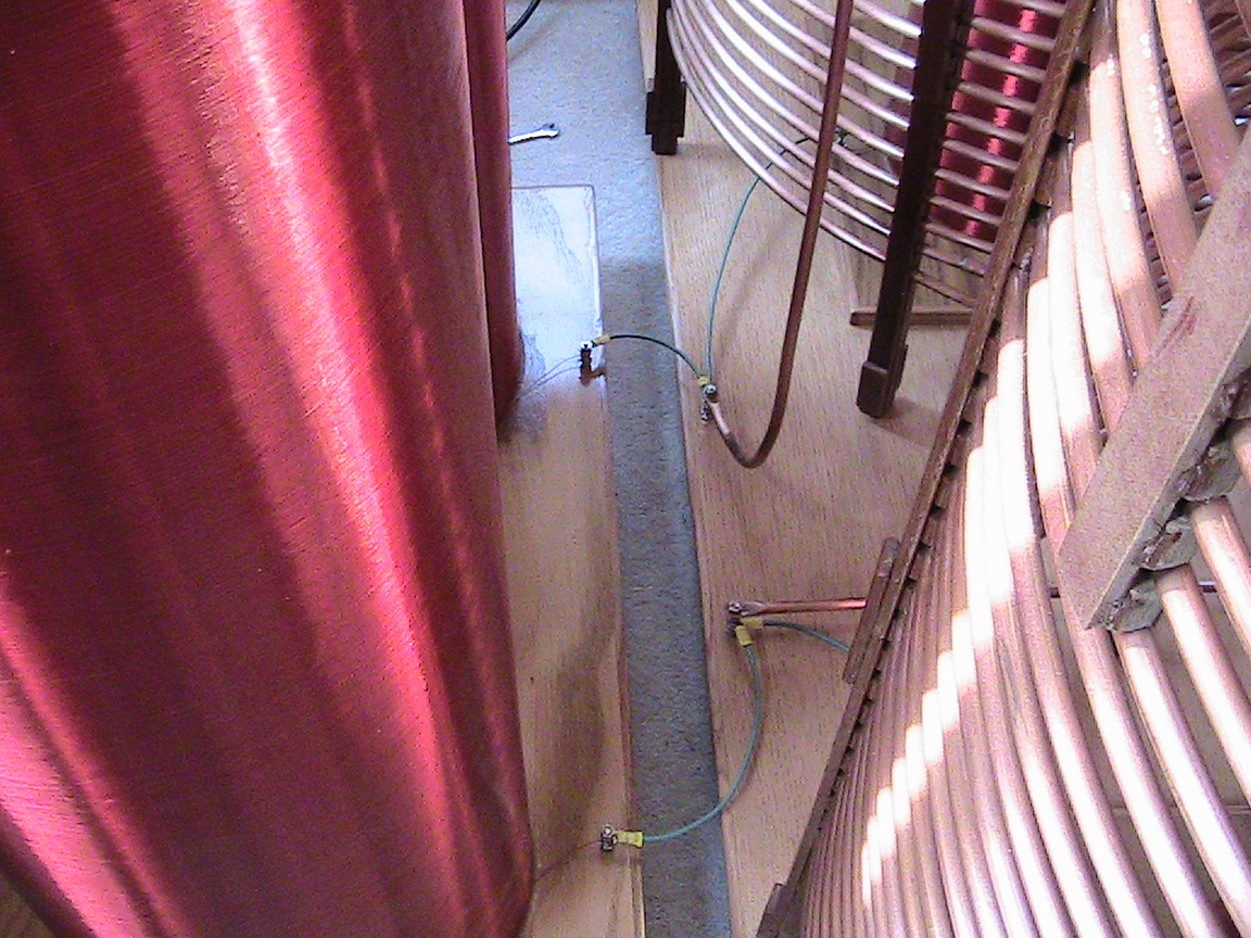
All of our tube structures are joined with compression fittings so we can easily assemble/disassemble. |
|
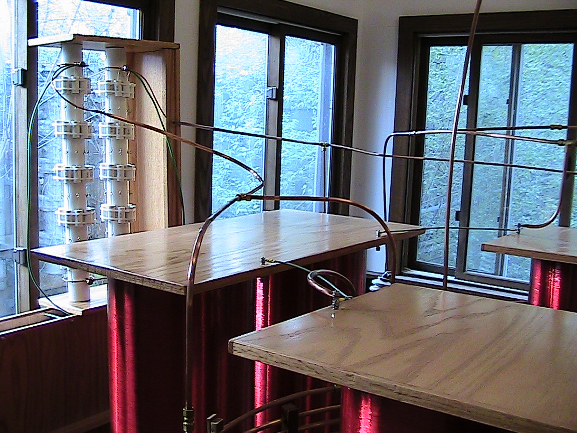
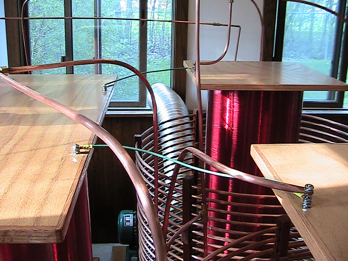
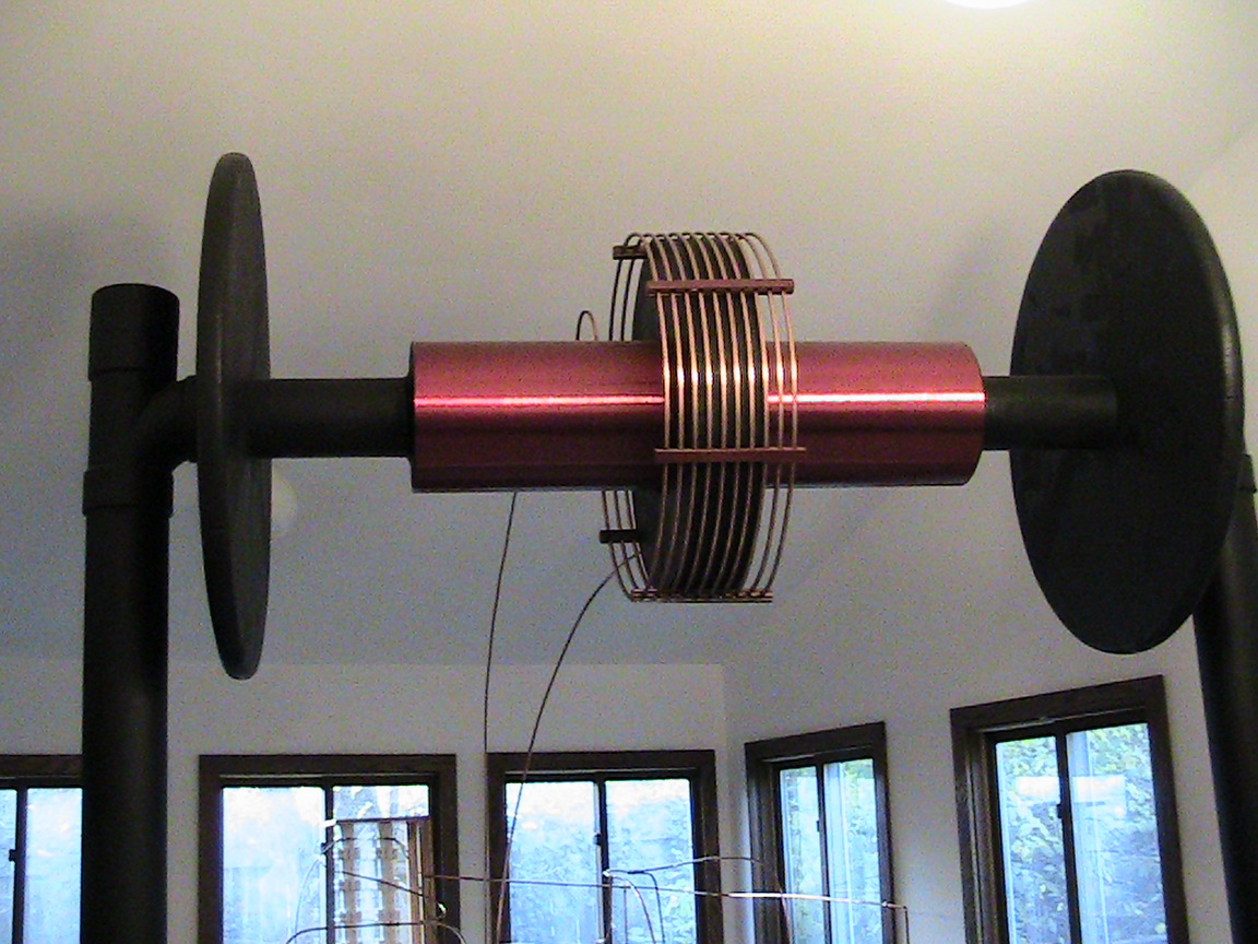
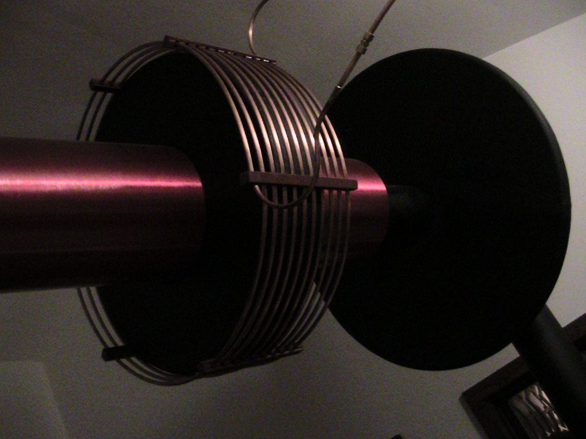
Each one-to-one balun has a half wave inside and a half wave outside. These half waves are wired across both the front end and the back end of the primary feed line. |
|
|
|
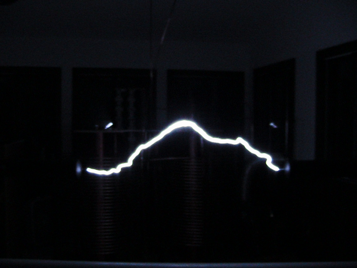
The top end capacitance is chosen entirely for minimizing the impedance for a given spark jump. We picked an opening of 52 inches and kept raising the top end capacitance until the unit no longer fired. Then we closed the jump to 48 inches (the length of the 1/2 wave inductor). This method ensures that voltage is the minimum required for reliable firing and the current is as large as possible (notice that our sparks are white hot). |
| We use Styrofoam for supporting the primary and for blocking the top end half wave, Styrofoam has excellent RF qualities. The top end disks are also aluminum foil covered Styrofoam. |
|
|
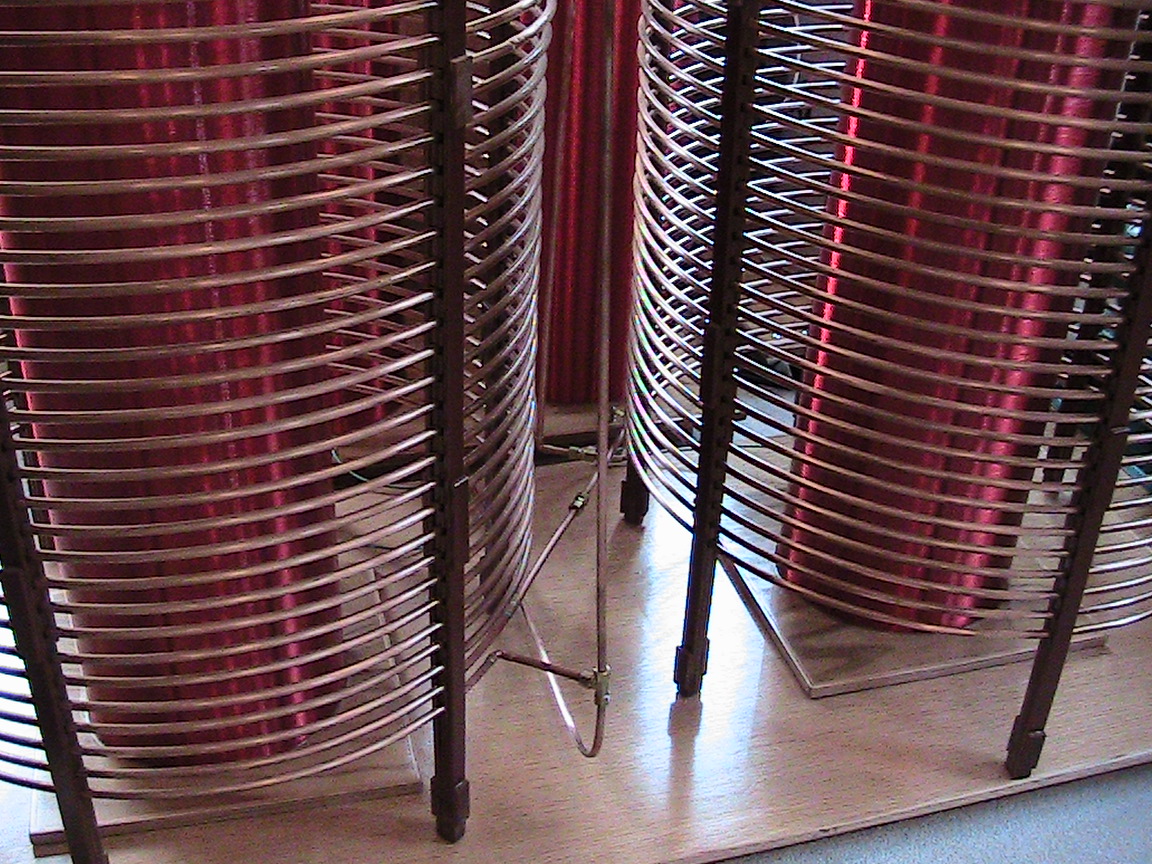
The primary needs a lot of turns and would normally be considered very over-coupled. However k between the magnetically isolated baluns lowers the overall system k to the point where tight coupling on the primary becomes a necessity. |
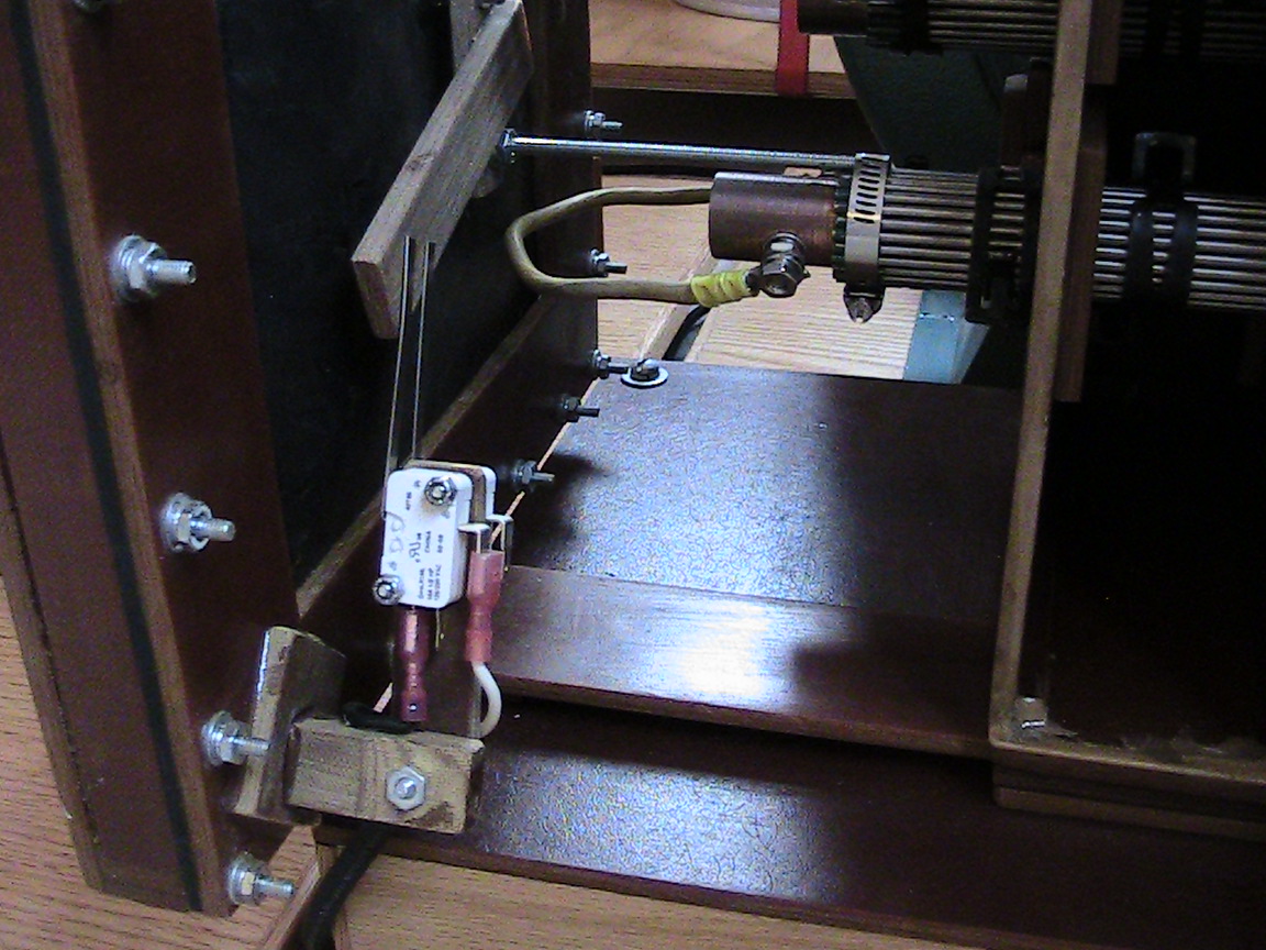
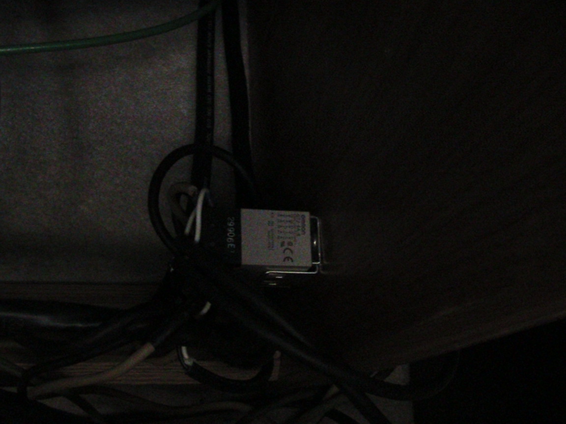
 A limit switch actuated by the vacuum diaphragm operates an
industrial control relay to provide proper sequencing.
A limit switch actuated by the vacuum diaphragm operates an
industrial control relay to provide proper sequencing.
|
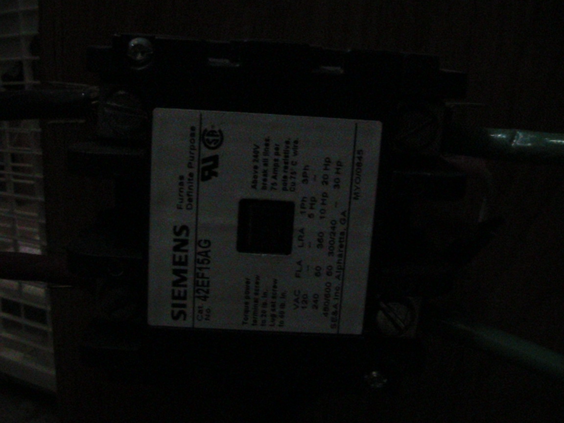
The high powered circuit for the transformer is switched by an additional heavy-duty relay. |
| When you build your box, make sure to leave a few inches space between electrodes. In fact make your box just a bit taller and deeper (but not wider), than the box shown as this makes adjusting the stops easier. |
|