Sherif El-Tawil, PhD, PE
Professor and Associate Chair
Department of Civil & Environmental Engineering | The University of Michigan
Progressive Collapse Modeling

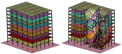
Progressive building collapse occurs when failure of a structural component leads to the failure and collapse of surrounding members, possibly promoting additional collapse. It is a complex, nonlinear dynamic process characterized by inelastic behavior, large deformations and contact/impact. Global system collapse will occur if the damaged system is unable to reach a new static equilibrium configuration. This research project investigates progressive building collapse, focusing on identifying the sources of collapse resistance, methods for quantifying robustness, the role of modeling approximations, and means for mitigation of progressive building collapse.
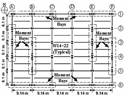
The National Institute of Standards and Technology (NIST) designed prototype steel framed buildings for the purpose of studying their response to an event which may cause progressive collapse. The buildings are 10-story office buildings with plan dimensions of 45.7 x 30.5 m and utilize moment-resisting frames as the lateral load resisting system. One of buildings designed by NIST is selected for the study in this paper: namely Building 3, located in Seattle, WA, and categorized as Seismic Design Category D, i.e. SDC-D. The building employs Special Moment Frames (SMF) for lateral force resistance.
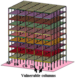
The selected building has a structural system comprised of both moment frames and a gravity system. There are 36 columns, of which 24 belong to moment-resisting bays, while the rest are gravity column. Beams in the gravity system are connected to the columns through shear connections which are comprised of single plate, shear tab connections, that are filet welded to the column and bolted using 22 mm, A23 high strength bolts to 9.5 mm A36 shear tabs. In the moment frames, reduced beam sections (RBS) are used with 50% reduction in RBS flanges. In all moment connections, beams are assumed welded to the columns, to simplify the modeling process. The structural steel used for all beams and columns is A992 (Fy = 345 Mpa). The plan of Building 3 is shown in Figure 1-a, while the elevation of the E-W frame on axis 6 is shown in Figure 1-b.

(a) Plan view

(b) Elevation of frame on axis 6
Figure 1: The prototype building
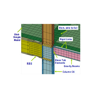
We have completed development of a highly detailed finite element model of the building in Figure 1. The model, termed M1, is shown in Figure 2. For reinforced concrete members, we model cracking, crushing, compression softening, and tension stiffening in concrete parts as well as yielding and rupture in steel reinforcement. For steel members, we model yielding, local and global buckling, and rupture. The main structural members in the simulation use a combination of shell, brick and bar/beam elements, which become inactive when critical values of stress, strain, or other damage indices are met.

(a) Full 3-D model

(b) Close up of connection region
Figure 2: Model M1
Detailed finite element model. The model contains about 1-million finite elements and runs for a week on a 24-CPU cluster.
The simulations, which are numerically intensive, address inelastic member behavior, separation of components from main structural system, falling motion and stacking in the rubble pile. The building model contains approximately 1-million finite elements and runs for a week on a cluster of 24 CPUs.
To accompany the main model, we have also developed three additional models: a model of the full 3-D system comprised of macro-elements for beams, columns and connections, termed M2; a 3-D micro model of a single frame in the system, termed M3; and a macro model of the planar frame modeled in M2, termed M4. While the Models M2 through M4 may not be as powerful and accurate as M1, they run in a much shorter duration. They are also quite accurate for the range of parameters for which they were calibrated and were therefore used for parametric and stochastic studies to identify the effects of uncertainties on structural response. For example, model M2 runs in 3 hours and renders a reasonably accurate simulation of 3-D response as opposed to about 60 hours for Model M1. Model M4 runs in about 1/1000th of the time needed for model M1.
The responses of the 4 models to collapse initiating events are compared to gain insight into the effects of the various modeling assumptions employed in the models and to provide added confidence in each of the models, since the modeling assumptions behind each model are different. The models are also exercised to develop a better understanding of 3-D structural system response and the influence of key variables during collapse events. Models M1 through M4, discussed above, are exercised within an Alternate Path Method (APM) setting.
Each model is first slowly loaded with gravity loads (i.e. dead load plus 25% of the live loads) over a 5 second period. Once the vibrations associated with process die down (typically over a period of 2.5 seconds), a member of interest such as a column is suddenly eliminated and the model is allowed to respond to the new boundary conditions. The response of the model is tracked by plotting various quantities of interest versus time, e.g. the force in members adjacent to the removed element, or the displacement of adjacent nodes. The progression of failure, if it occurs, is also tracked and recorded. These responses are then compared to corresponding quantities computed from other models to achieve the objectives of the study. Comparisons between M1/M3 or M2/M4 shed light on the effect of the slab and 2-D versus 3-D modeling. Similarly, comparisons between M1/M2 or M3/M4 highlight the effect of using macro-elements to represent steel frame response. These runs yield insight into structural collapse response and the key assumptions that many engineers and researchers resort to when conducting such simulations.