Stepper Motor Motion Control: Print Carriage Transportation in Xerox Printers Client: Xerox Duration: Fall 1999- Spring 2000 Team: Prof. Kevin Craig, Shorya Awtar Mechanical Engineering, RPI |
||
Problem Statement: The C-6/C-8 series of Xerox color printers is prone to vibration and noise during the ink carriage transportation. The carriage is driven by a stepper motor and driver chip system. The objective of this project is to eliminate the undesirable noise, improve print speed and quality by analyzing the stepper motor system, and suggest mechanical and electronic design modifications. Project Description: Stepper motors are incremental actuators that can run in open-loop mode with sufficient accuracy. While stepper motors have this advantage, it is necessary to address issues related to motor instability, loss of synchronism and high vibration levels in the design of stepper motor systems. Based on the application, a suitable driver chip is selected and an appropriate stepping mode (full, half or micro step) is decided. A pre-determined sequence of step-states is then used to energize the motor windings and thus cause successive steps of motion. This step-state sequence table is stored in the memory of a microprocessor. Based on step table information, the microprocessor sends digital signals to the driver chip at appropriate times. Whenever the driver chip receives a trigger signal from the microprocessor, transistors within the chip switch states such that the next step-state of the motor gets energized. For peak performance it is necessary to generate an optimized step sequence table. A typical desired motion profile is illustrated in the following velocity vs. time curve.
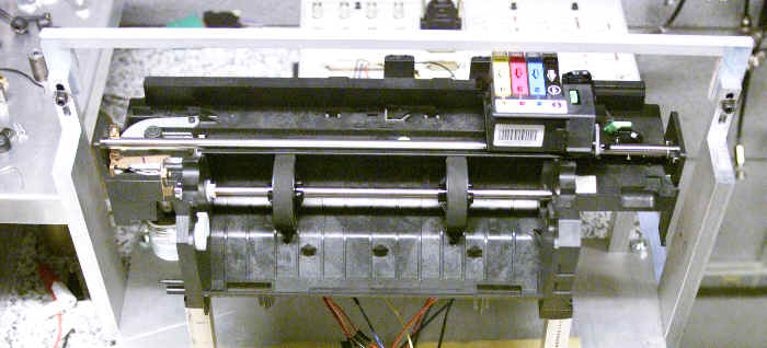
Figure 1 The carriage is required to accelerate to the print speed level in short time within a specified distance, move at constant speed while printing takes place and finally decelerate to rest. This motion is to be performed repeatedly in both directions. To analyze the stepper motor motion control issue in the printer, we have designed and assembled a test-rig. Essentially, the printer is stripped down and only the carriage transportation sub-unit is retained. The test system is equipped with sensors to measure the motor and carriage velocities. The motor is driven by means of a standard PWM current control driver chip. Command to the driver chip is sent from the computer using the real time control prototyping tool D-Space which has a Simulink interface.
Figure 2. Experimental test-rig
It is realized that sharp changes in acceleration, as is the case in Fig.1, introduce a jerk in the motion and cause an oscillatory velocity response. So the first step in improving the stepper motor motion quality is to optimize the intended velocity profile. Instead of using a constant acceleration, followed by zero acceleration and then deceleration, we propose a smoother profile that has no discontinuities in the acceleration variation. We use a fourth-order curve for velocity ramp-up and decay. This ensures that the intended velocity gradually increases from the zero value and reaches the constant velocity, and similarly while decelerating, the velocity gradually comes down to zero. We refer to this as the ‘smoothening of the velocity profile’ and at a later stage, it is experimentally confirmed that this not only improves the motion quality but also makes the system immune to parameter variations.
Figure 3. An optimized velocity profile where sharp corners have been smoothed out
Once an optimum velocity profile has been defined, the next stage in the design procedure is to generate an optimum step state sequence. To accomplish this, a model of the electromechanical system is developed. Torque-balance method is used in modeling the stepper motor and generating a step-state sequence. Since this requires multiple calculations, it is implemented using a computer code. After a preliminary step sequence has been generated, it is further optimized by means of a look-ahead correction technique which is an iterative procedure. The resulting sequence is then used for running a simulation of the system. Finally by means of D-Space, the calculated step sequence is tested on the experimental test-rig. The experimental result, i.e. the carriage velocity measured, is compared to the intended velocity profile and simulation predictions. These results are studied to gain a better understanding of the stepper motor operation.
Figure 4. Comparison of the actual carriage to the intended velocity Accomplishments: The system of stepper motor, timing belt and pulleys, and load was studied and modeled. Based on this model, optimized step state sequences were generated to achieve various motion and velocity profiles. A comparison of different motor-driver systems was made and the results were provided to the client. Skills learned:
|