|
DC Motor Motion Control Client: Pitney-Bowes Duration: Summer 1999 Team: Prof. Kevin Craig, Shorya Awtar Mechanical Engineering, RPI |
||
|
Problem Statement Certain high-speed document handling machines manufactured by Pitney Bowes exhibit the undesirable phenomenon of high frequency ringing and vibrations. This is attributed to compliance in the system e.g. finite motor-load shaft stiffness. The objective of this project was to study and analyze a simple test bed that had all the relevant attributes of the more complicated machines. The dynamics and control of a load driven by a Brush-less DC motor was to be investigated in the context of high-speed high precision motion control.
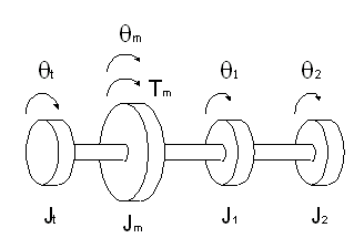
Project Discussion: The fundamentals of ‘brush-less DC motor’ operation were studied. Implementation issues and associated driver circuitry were investigated. Based on these, an analytical model for the motor-driver system was obtained. All this information was compiled in form of a case study for brush-less DC motors. To investigate the motion control problem, we used a simple test bed which consisted of a motor, flexible coupling and multiple load inertia. For the sake of experiemental simplicity a brush DC motor was used instead of a brushless DC motor. The choice of brush-less DC motor would require additional driver circuitry and a more complex command signal for operation. A conventional DC tachometer was employed to sense the motor velocity. In fact, the motor and tachometer used were integrated in a single unit and had a common rotor shaft. The motor was operated in 'current-mode'. A schematic of the physical system is shown in Fig. 1.
Figure 1. Physical System
The above set-up was analytically modeled as a four-mass three-spring system.
Figure 2. Physical Model
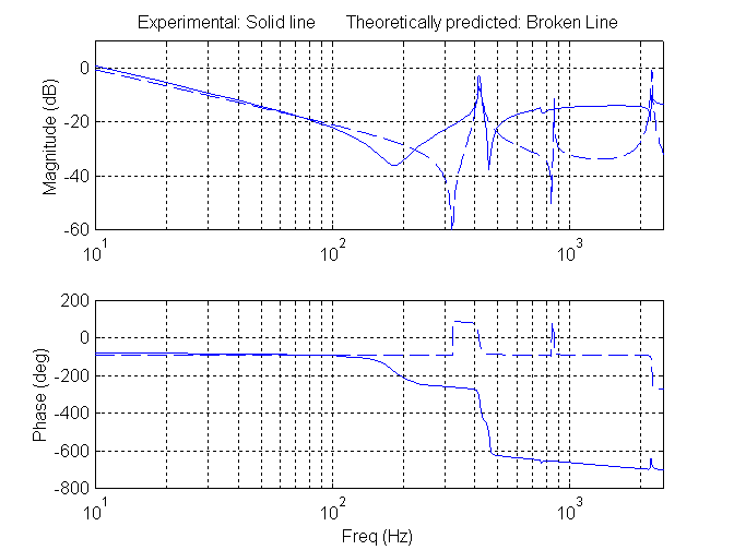
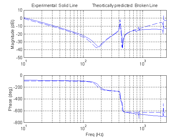
Using conventional DC motor and tachometer relationships, a transfer function was derived between the motor input current and tachometer output signal. Based on this analytically obtained model, an open-loop frequency response was obtained for the system. At the same, an experimental frequency response was generated using the DSP hardware/software tool SigLab. SigLab sends a sinusoid signal of increasing frequency as input to the system (motor current), and records the corresponding system output (tachometer voltage). Based on this input and output data, SigLab generates the frequency response for the system. Quite surprisingly, the experimental result did not match the analytically predicted frequency response in the high frequency domain (Fig. 3). Since the high frequency open-loop response significantly affects close-loop performance, it became necessary to obtain a more accurate model for the over-all system. After close investigation, we found that a weak mutual inductance between tachometer windings and the motor windings results in a higher order tachometer dynamics. Consequently, an accurate model for the system was obtained by incorporating the tachometer dynamics, which indeed predicted the experimental results very precisely (Fig. 4), and thus verified the new model. An investigation of this ‘magnetic coupling effect’ resulted in my Master's thesis.
Figure 3. Comparison of experimental response and predicted response using conventional model
Figure 4. Comparison of experimental response and predicted response using the proposed model
Skills learned:
Previous: Stepper Motor Motion Control Next: MS Thesis Research
|


