The
Army wants a machine to test army boots for durability. This machine
should mimic, as closely as possible, the geometry and forces of a
typical soldier walking (Fig. 1) in combat boots. It should repeat this
motion for an unlimited number of cycles until the boot leather breaks
down. The single boot will be fitted to a prosthetic foot that is
attached to the test machine.
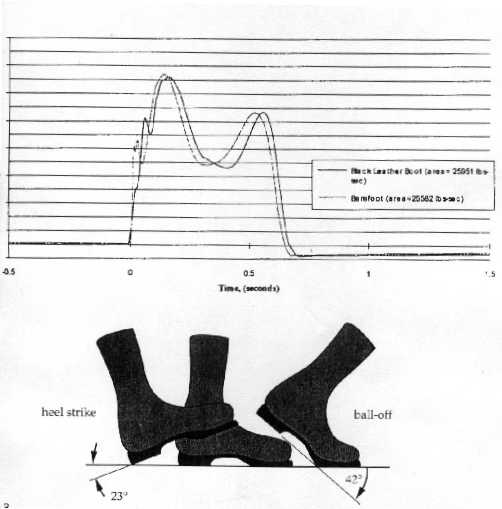
Figure 1. Geometry and forces of walking motion
Project
Discussion
The design was decomposed into two sub-problems:
first, to deal with the kinematic aspects of design and then second, to
incorporate the force requirements. The first stage was to simulate the
walking motion, an exercise purely in kinematics. A mechanism (Fig. 2)
was conceived that would mimic the geometry of walking. The ternary link
(in shape of a right-angle triangle) was constrained by two arc-shaped
slots, and was driven by a crank through a coupler. The link-lengths
were chosen such that the ternary link exactly replicated the geometry
of walking motion. The mechanism thus designed was a complex four-bar
linkage.
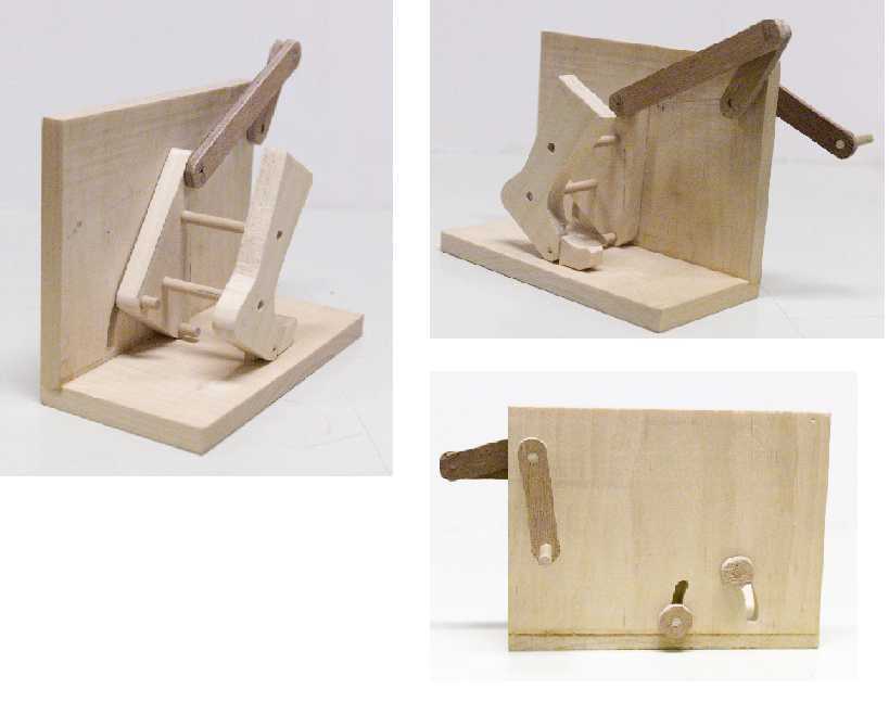
Figure 2. Prototype to demonstrate the simulation
of walking motion (kinematic requirement)
To
this triangular link was connected a prosthetic leg, as shown in the
picture. Now moving to the second stage, the goal was to produce an
appropriate contact force varying with time, during the motion. To
accomplish this, the prosthetic foot was rested on a base that could
slide on vertical guide rails (not included in the above prototype). The
force was generated by means of a cam follower assembly, where the
follower was a spring loaded between the base and the cam. Inputs to the
cam and the linkage mechanism were coupled. The cam profile was designed
such that it would produce a suitable deflection in the follower spring
and thus cause an appropriate force on the foot. With both the kinematic and dynamic
requirements satisfied, the design for the
machine was thus complete.