1.0 Application of ACGIH TLV® to case pacing job
- In this exercise, you will:
- conduct and analysis of steps and forces that determine the force patterns necessary for packing boxes into cases.
- apply the ACGIH TLV for localized fatigue to determine if the force duty cycle and average workforce exceed recommended limits.
- determine how much additional recovery time is required to prevent localized/arm fatigue
- Discuss administrative and engineering job improvements for reducing fatigue.
2.0 Casepack job:
- Objectives: Pack 12 boxes of product into cases suitable for shipping
- Production rate: 240 cases/hr (Takt time = 20s/case)
- Schedule:
- Shift:strong> 8 hrs
- Breaks: 15min AM & PM, 30 min lunch
- Materials:
- Boxes each w/3-8 oz bottles (0.5 lb or 0.23 Kg) -- 2.3 in x 5.9 in x 6.6 in(58.42 mm x 149.86 mm x 167.64 mm)
- Cases:10 in x 20 in x 7 in(254 mm x 508 mm x 177.8 mm) (erected; holds 12 boxes)
- Work Station: See Fig 1.
- Roller conveyor:
- 28" high x 10" deep (711 mm x 254 mm)
- Conveyor + open case (flaps up) heiht: 38.5in (978 mm) high
- Conveyor + case+ box: 44.5in (1130mm) height:
- Note: worker must reach over open flaps to get & pack boxes.
- Work Method:
- Get/position pre-erected cases on left
- Pack 12 boxes, 2 at a time alternating right and left hands.
- Fold case flaps closed
- Aside filled cases into the tapping machine
 (a) |
 (b) |
 (c) |
3.0 Determine movement times/patterns
- Traditional time study methods:
- Time-based analysis of work methods and forces: inspect video recording of a job at fixed intervals and record: action, posture, and force.
- Event-based analysis: Inspect the video recording of the job and determine the time at which each action begins and ends, along with posture and force.
- Time study Tools:
- Video recorders and players computers, tablets, phones
- Specialized apps
click here to download (a) |
 click here to download (b) |
Fig 2: movement patterns and forces for right and left hands. Forces may be estimated based on observation and verified using biomechanical analysis (see next section) or instrumentation. Force estimates elements are grouped based on common forces.
4.0 Determine required strength
- Worker ratings (for each each step)
- Biomechanics: (Fig 3 in section 2.4 Biomechanical analysis of task hand force demands)
 Pinch force = Weight / (2xCoF) (a) |
Pinch Force to hold a 15N (3 pound) paper box: Moist skin: Fp ≥ 15N / (2 x 0.50) = 15N (3 pounds) Dry skin: Fp ≥ 15N / (2 x 0.25) = 30N (6 pounds) |
Fig 3: The pinch force required to keep box from slipping out of the hand is related to the object weight and the coeficient of friction, CoF (a) (a) and left hand (b). Friction Data.
5.0 Determine the strength capacity of worker population
6.0 Determine %MVC for transferring boxes to shipping case
Table 1: %MVX calculations for 30-39 year-old male and female left-hand are shown in Table 1. pinch strength.
| Male | Female | |
|---|---|---|
| Pinch Strength | 114.7±24.5 N (25.8±5.5 Lb) | 78.5±18.6 N (17.6±4.2 Lb) |
| Required Pinch (moist skin) | 15N (3Lb) | 15N (3Lb) |
| %MVC | 13% | 19% |
| Required Pinch (dry skin) | 30N (6Lb) | 30N (6Lb) |
| %MVC | 26% | 38% |
How would %MVC be affected by inertia?
What would %MVC be for someone with 25%female strength?
What other factors can affect strength and realtive workload?
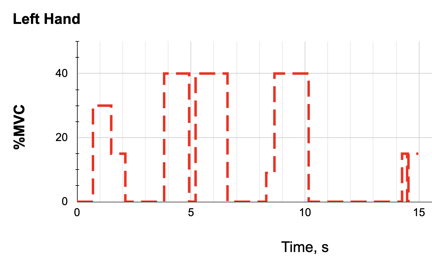
7.0 Combining force and movement patterns
 (a) |
 (b) |
 (c) |
8.0 Applying the TLV®
- Determine the maximum recommended %Duty Cycle for the given %MVC.
- Compare the observed %Duty Cycle with the maximum recommended %Duty Cycle.
- How much should the recovery time be increased or the average %MVC be decreased?
- Determine the maximum recommended % %MVC for the given %Duty Cycle.
- Compare the observed %MVC with the maximum recommended %MVC.
- How much should the %MVC be reduced?
 |
9. "Model-based job/task analysis"
Predetermine time systems
Movement times in the above case packing example were determined from a video recording (Fig 2). It was assumed that the observed worker was “qualified and trained, following a standard method, working under normal conditions (environment, tools, and materials), and working at a normal pace.” These conditions are the basis of what time study engineers call “normal time” and standard time. These conditions ensure that work is performed consistently in the same manner and make it possible to predict the time required to complete various operations in manufacturing and other industries. They also make it possible to assess ergonomic stresses and anticipate how ergonomics stresses are affected by variations in the underlying assumptions about tools, materials, methods, and environmental conditions.
Models have been proposed for predicting normal times based on the characteristics of each action or movement (Freivalds and Neibel 2009. Examples of these include: “Motion-time analysis - MTA,” “Work-factor,” Methods-time measurement - MTM,” “Maynard operation sequence technique -- MOST,” and Modular arrangement of predetermined times - MODAPTS.” MODAPTS stands out as a simple and widely used system.
- MODAPTS models movements into six categories designated as M1, M2, M3, M4, M5, and M7 based on the body part or move distance.
- The “M” indicates distance, and the number indicates the body part and allocated time in “Mods.”
- One mode equals 0.129s, which is the basic motion unit for MODAPTS.
- Reaching for the boxes and Moving them to the shipping case involves moving the hand to and from the limits of the shoulder and is classified as M5.
- Movements are always followed by a “grasp” or “position” terminal element.
- MODAPTS does grasp and position each as three categories based on the complexity of the action, G0, G1, and G3 and P0, P2, and P5. In each case, the letter indicates the action and the number indicates the time.
- Grasping the cases in the above example is classified as G1 because it requires deliberate finger motion to gain control over the work object and because there is no interference from adjacent materials of structures. Position the boxes in the case is classified as a P5 because it requires deliberate attention to position the box along two axes.
Application of MODAPTS to case packing
- The motions required to pack one box in MODAPTS are:
- M5+G1+M5+P5
- The cycle time for packing one box with one hand, Tcycle, is:
- Tcycle=5+1+5+5 =16 Mods
- G1+M5+P5 and Twork=1+5+5=11 Mods
- The Duty cycle for packing one box can be computed as:
- %DC = Twork/Tcycle = 11/16=69%
- Recall that the worker alternates right and left hands, which means one hand rests while the other works. The total cycle time for one hand is equal to the cycle time for the right hand plus that of the left hand. So the duty cycle for each hand can be computed as:
- %DC = 11/(16+16)=34%
- All of these times can be converted to seconds, but it is not necssary for computation of duty cycle.
Summary
This is perhaps an oversimplification of a simple task. Still, the duty cycles compare favorably with the values obtained from the analysis of the video recording in Figure 4. A closer analysis might find that additional time is required to put the boxes into the case. Packing the boxes into a case might be modeled as G1+M5+P0+M3. This is the power of predetermined time systems. They enable the user to examine each step of the task closely and determine how each affects the burden on the worker. Predetermined time systems are an important tool evaluating and controlling fatigue.
The references below will also demonstrate the use of CAD models for analysis of the spatial relationship betweent he worker and work.
References:
- Freivalds, A. and Niebel, B.W., 2009. Niebel's methods, standards, and work design. McGraw-Hill, 12th edition 2009, p 501.
- MODAPTS, MODular Arrangement of Predetermined Time Standards
- Predetermined Motion Time System Calculate Standard Time Using MTM, MODAPTS or MOST
- see: Armstrong T. CAD and MODAPTS Models for Assessing Localized Fatigue. International Ergonomics Association Meeting, 2021
- CAD models can be constructed using AutoCAD, SketchUp, and other tools to determine required movement patterns and postures.
10.0 Solutions?