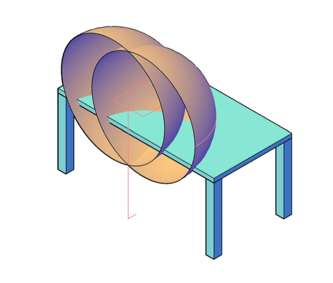
The primary goal of this exercise is to create 3-D model that shows the spatial relationship between
a worker of a given size and a workstation of a given size (see Fig 1).
A secondary goal is to familiarize you with the AutoCAD features and controls for constructing this and similar models.
This exercise will use height data from the National Health Survey2,
and link length data from Drills and Contini (1966)3 to create a model that can be used to explore the spatial
relationship between a worker of a given size and a work bench of a given size.
Workplace and worker parameters for this exercise see:
Reach Limits
Iinformation for creating your model:
Bench:
Width: 2.0m
Depth: 1.0m
Height: 0.9m
Top thickness: 0.05m
Legs: 0.1m x 0.1m
Worker (5%female height2 and average proportions3
Stature: 1.504m
Floor-Shoulder: 1.230m
Distance between shoulders ÷2: 0.194m
Arm+Forearm+Hand: 0.663m
Floor-Hip: 0.797m
Distance between hips ÷2: 0.144m
Location/position:
Facing Bench
Center on long side
Distance away from edge: 0.10m
Fig 1: Workstation model showing bench and short female (5%tile height) worker.
AutoCAD
This exercise uses AutoCAD1. There are many CAD programs available that can be used to create aadequate 3-D worker-workstation model.
AutoCAD is widely used in industry and it will be a nice addition to your cv.
There are a number of excellent on-line tutorials that will help you quickly acquire the necessary skills.
The Hitchhiker's Guide to AutoCAD Basics
or go to Youtube.com and search on the topic interest.
Note: AutoCAD comes in two flavors. One for Mac OSX and one for Windows.
You will find differences between the menu layouts for the Mac and Windows versions.
The command pallets for the Windows are above the drawing space.
The command pallets for the Mack version are on the left.
You can't make the Mac version look like the windows version or visa versa.
Commands are very similar. The difference between the Mac and Windows versions is diminished if you use Keyboard shorcuts and the command line or dyanamic menu.
Open AutoCAD by clicking on AutoCAD in your Applications folder (or where ever you store your apps).
Depending how AutoCAD is configured, you may be asked to selected a template. The template affects how you display your model.
You don't really need to worry about it now as we will be focusing primarily on the creation of a model. If asked, selected the acad3D.dwt temaplate.
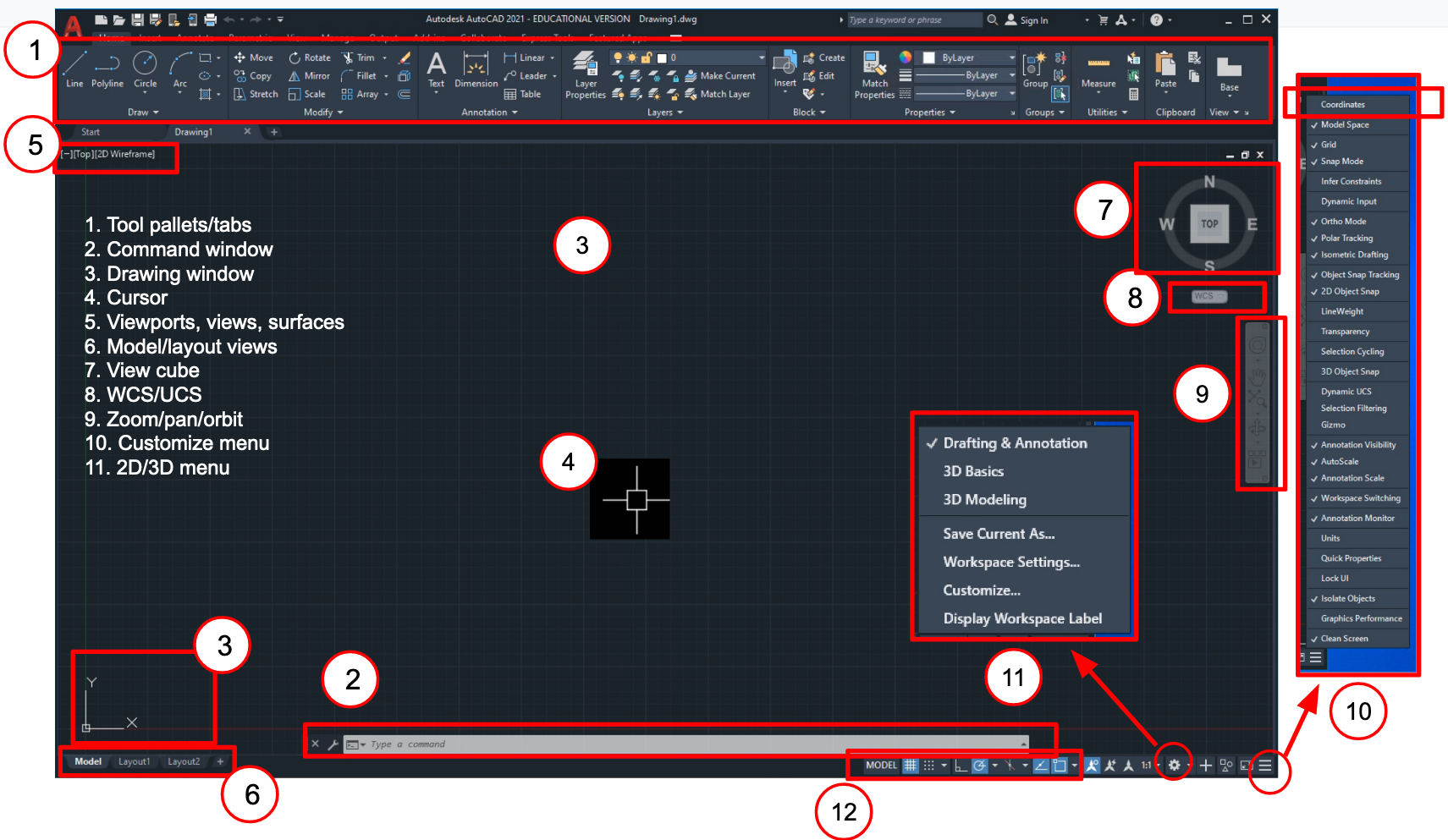
Fig 2: AutoCAD Windows Desktop.
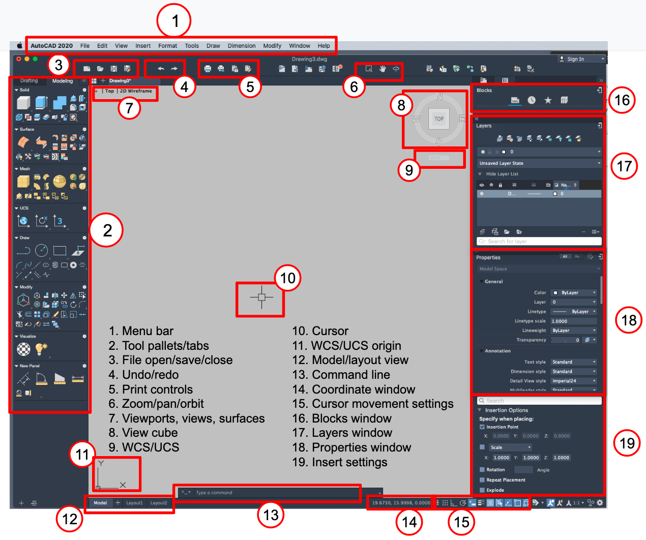
Fig 3: AutoCAD Mac Desktop.
Drawing area
The drawing area in AutoCAD by default is black with white lines. This is a legacy of the days when Computer displays were CRTs.
You can change the color options using the "PREF" command.
You will see an xy or xyz symbol in your drawing area depending if you are in a drafting mode (2D) or model mode (3D).
The coordinates of the cursor with respect to the origin in the coordinates window in the bottom of the screen.
Note: the Coordinates window will not by shown by default in the windows version.
You must go to the icon in the lower right corner to open the customize window and select "Coordinates."
Depending on how you have autoCAD configured or what template you specified, it may open showing a planner view of the xy-plane or
it may show an "isometric" or "iso" xyz view
Note: Assume that the drafting tools work only in the xy-plan. You can use the "UCS" or "USER COORDINATE SYSTEM" to create an arbitrary xy-plane as needed.
You can easily switch between views.
For the Mac simply click on the view cube in the upper right corner to indicate the view that you want
or use the "Orbit" command to change the views.
Select the Drafting (2D) or Modelling (3D) tool pallets using the tabs at the top of the tool window on the left side of the window.
For a windows machine, you can also use the view cube to change the view, use the icon in the lower right corner to specify "3D" or "Modelling" to see the modelling tool pallets.
Many of the commands in AutoCAD will query you for starting and stopping locations.
Drawing units
AutoCAD work in arbitrary units, so it is up to the user to keep track of inches, feet, meters and centimeters.
While AutoCAD enables you to specify drawing limits, this is for setting default zoom limits.
The "LIMITS" command does not restrict the size of your drawing. You can start anywhere and, for practical purposes, make your drawing as large as you want.
It is advisable to specify drawing units though, to avoid scaling problems if you import or export drawing objects to or from your model.
"UNITS" allows you to indicate if you will be working in decimals or fractions, the precision, and insertion scale units (mm, cm, in, ft, etc.), among other things.
For this exercise we will work in decimals, meters and a precision of 1mm (0.000)
Other useful settings include: "SNAP" and "ORTHO.""
Constrain the movement of the cursor making it easier for you to move to exact locations.
Can be turned on and off on the fly using the menu in the lower-right corner of the AutoCAD window.
View "ZOOM," "PAN," "ORBIT"
Click on commands in menu
Enter commands into command line
use 3-Button mouse
PAN -- hold mouse wheel down and move mouse
ZOOM -- rotate mouse wheel
ORBIT -- hold shift+mouse wheel and move mouse
Layers
Create and label one layer "bench" for the bench
If it is not open, open the layers window (type "LAYERS" into the command line or select it from the tool pallet)
Click on the new layer symbol in the layer window. Layers will be named Layer1, Layer2, .... by default. Click on the default layer name until it lights up and over type the desired name.
Repeat to create layer "f5"
Make layer "bench Active"
You can use the layer window to change the line type, thickness or color for all objects in that layer.
You also can change the line properties for individual objects using the properties window. Either right click on object of interest or type "PROP" into the command line and select object of interest.
Create and label on layer "f5" for the worker.
Repeat: make layer "bench" active
Viewports
The "VIEWPORTS" Command enables you to view your model from different views at the same time
You will find this very helpful for creating and studying models
Practice
Make a model of a workbench 2m wide x 1m deep x 0.9m high
Vary the ortho and snap functions until you find the fastest way to create your model
Try out the various ZOOM, PAN and ORBIT tools.
"Construct bench" is defined as task 1.0.
Task 1.0 "Construct bench" is divided into two subtask:
1.1 "construct top" and
1.2 "construct legs"
There are many ways or methods for completing subtasks 1.1 and 1.2. We have chosen a method that is realtivly efficient and has some useful didatctic value.
Task 1.1 Construct Benchtop
use rectangle tool "REC" to construct a 200cm wide × 100cm deep rectangle in the xy-plane.
AuotoCAD will prompt you to enter the first point.
Point and click with the mouse
The grid snap function will be a big help if you select this option.
Or enter the values into the command line as requested
It may be helpful to enter the first coordinate at a round number , e.g., 1,1 or 10,10.
That way the values in your coordinate window will also be roundnumbers and easier to read.
Select the "EXTRUDE" tool from the modelling pallet or enter into command line
Select rectangle by clicking on it or using lasso tool
Return when done
Move cursor upward to project rectangle into thrid dimension.
stop at 0.05m or 5cm or just enter value into command line.
you now have the top, but it is on the floor.
Select "MOVE" tool or enter into command lines
AutoCAD will prompt you to select object
Select bench top by clicking on it or using lasso tool
Enter return when done selecting objects
Wnen prompted, select arbitrary reference "base" point on bench top.
Move curson upward in the direction you want to move the top.
Note you will see a line extending from the reference point and the cursor --
be sure that the line is parallel to the z-axis (it will alternate short and long dashes when parallel to the x, y or z axis).
You can move it to exactly 85cm or 0.85m and click the mouse or your can just type 0.85.
The default view will be a wire from. Change it to a realistic view using the dropdown menu in the upper-left corner of the drawing spance
Task 1.2: Construct Legs
Use the view cube or the "ORBIT," "PAN," and "ZOOM" tools to position your top for a good view of the bottom.
Use the "RECTANGLE" tool to make a 0.1mx0.1m cross-section of the leg -- be sure that "Object snap" is on.
Use the "EXTRUDE" tool to extrude the leg 0.85 downward to the floor.
Repeat 3x for other 3 legs or use "COPY"
Copy legs
Select "COPY" from menu or enter "COPY" into command line.
When prompted click on leg to select it and then enter return to end selection.
Select reference point at top of leg the corresponds to outer corner of bench.
Select corner of bench to complete copy move.
Repeat copy, but this time select and copy both legs to opposited side or end of bench.
Task 1.3 Cleanup Model
The "GROUP" command will preserve the spatial relationship of your bench parts and help you avoid accidental changes
Enter the "GROUP" Command
When prompted click on top and each leg or use lasso tool to select all bench parts.
Enter return to complete selection and form group.
Use the "Layers Window to choose a color for your bench"
If desired, export worker as a "BLOCK" or "WBLOCK"
Practice
Repeat this exercise instead of the rectangle tool try using the "LINE," "POLYLINE," and "BOX" tools.
What are the advantages and disadvantages of each?
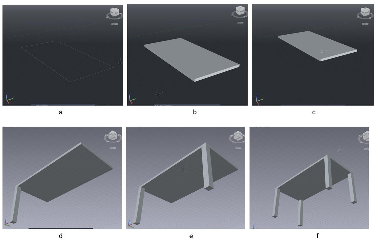
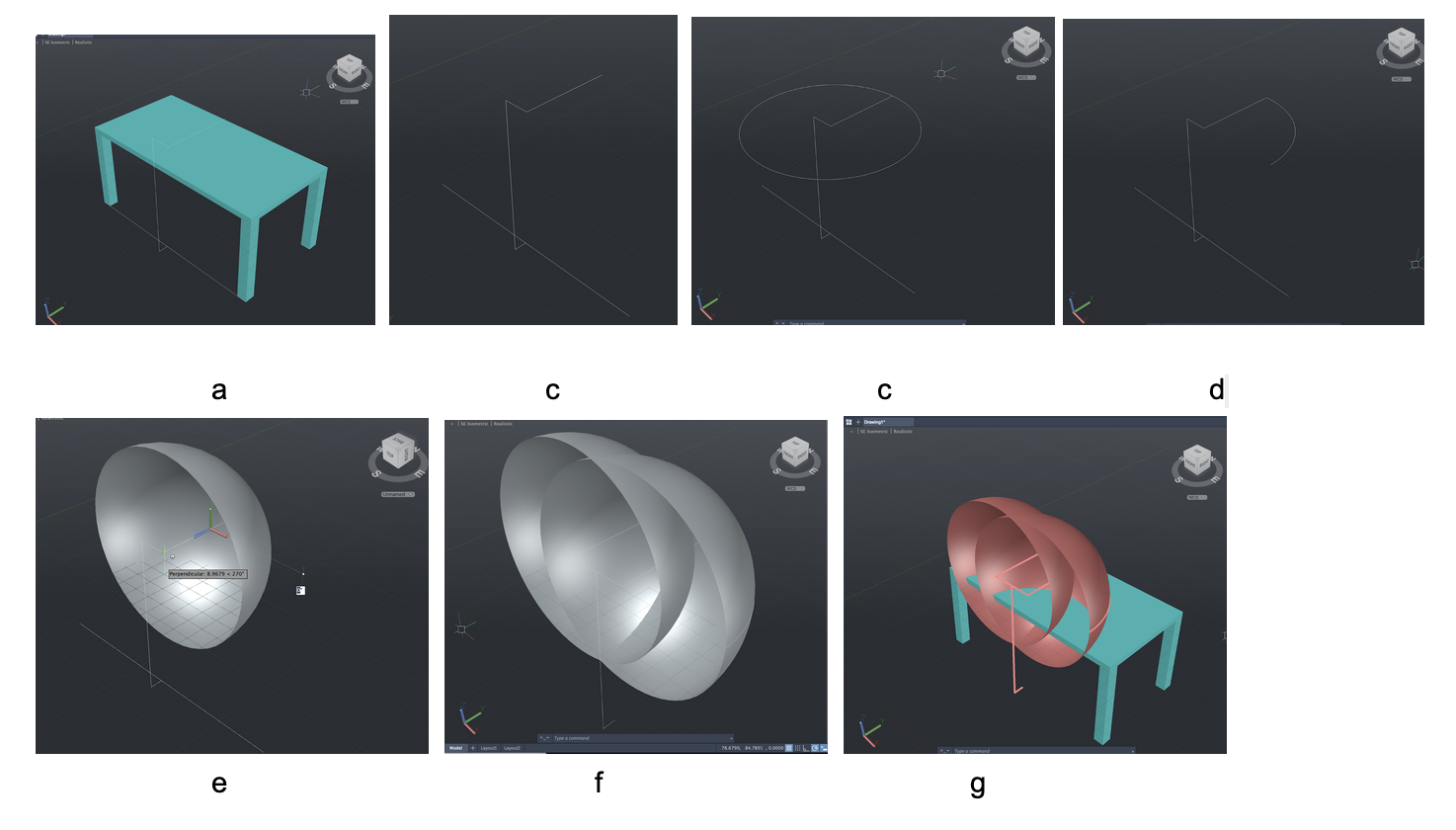
Fig 3 Workbench construction: Use of a) "RECTANGLE" tool to create bench surface in xy-plane;
b) "EXTRUDE" tool to give bench top thickness (Change surface to "Realistic");
c) "Move" tool to move bench top to desried height;
d) "RECTANGLE" tool to create cross secion of leg on underside of bench; use "PAN," "ZOOM," and "ORBIT tools"to position bench
e) "EXTRUDE" tool to extend leg from bottom of bench to origin;
f) "COPY" create a second leg from the first).
g) "COPY" create a third and fourth leg from the first and second)
Use "GROUP" to preserve the spatial relationship among the parts of the bench. Use the "Layers Window to choose a color for your bench"
Construct stick figure and touch reach limits for a worker with 5%female stature2 and average body proportions3
Select "f5" layer from "Layers Window"
Task 2.1: Create stick figure:
Use line tool to draw a line from outer-bottom corner of bench legs closest to workers
Make sure that Object Snap settings include object midpoints
Set "ORTHO" on
Starting at the midpoint of the line between the bench legs create a 0.1m line away from the bench parallel to the y-axis
Continue upward parallel to the z-axs 1.230m (shoulder height)
Contine parallel to the x-axis 0.194m to the right shoulder
Continue parallel to the y-axis 0.662m from the shoulder to the finter tip.
Enter "return" to complete your line
You might care to extend the line from the center of the body to 1.504m (5%female Height)
You can add hips and legs, but you might want to leave a leg in the middle as a reference point.
Tasks 2.2: Create reach hemispheres
Use the "CIRCLE" tool to draw a circle arond the should with a radius equal to arm length
Use the "TRIM" tool to remove 3/4 of circle - When viewed from above, arc should extend 90° clockwise from the finger tip
Use the "REVOLVE" tool to revolve the arc 360°about the outstretched arm -- should should now have a reach hemispher for the right arm
Use the "LINE: to to construct a line 0.194m from the center of the body to the left shoulder.
Use the "COPY" command to copy the right arm and reach hemisphere to the left shoulder -- hint: a wire frame view will make it easier to locate the reference points for the move.
Task 2.3: Finish Model:
Use the "GROUP" command to preserve the spatial relationship between the parts of your worker
It is sometimes helpful to preserve the links and the the reach hemisphers in separage groups or even separate layers.
If desired, export worker as a "BLOCK" or "WBLOCK"
Now create a new layer and model of a worker with 95%tile height.
Fig 4 Worker construction: Use of a) use "LINE" tool to creat a line between bottom corner of legs; Hide bnch Layers.
b) "POLYLINE" tool to create stick figure starting at midpoint of line.
c) "CIRCLE" tool to construct about the shoulder in xy-Plane;
d) "TRIM" tool to create a 90° arc about shoulder);
e) "REVOLVE" tool to rotatate arc 360° about arm & form open hemisphere,
f) "COPY" tool to create second arm and hemisphere about left shoulder.
g) Use "GROUP" command to group worker parts. Use "ERASE" to remove line on floor. Select color for worker. Show bench layer
Your model of the small and large workers and the workbench is a very power tool for evaluating the and designing workstations.
This model will enable you to determine with a high degree of accuracy if most workers will be able to reach a given work objec without bending or twisting.
It will enable you to concisely specify where to locate a work object on the bench to reach an object or in some cases avoid touching work object.
You can construct work objects and construct a virtual workplace and be confident that most workers will be able to use them.
you can use a virtual work space to deterine reach and move distances and comput normal work times use MODAPTS5 or other predtermined time systems.
Turn tags on and off to compare reach limits for large and small workers.
Here are some tools to explore that will help you explore your workstation model.
Use "ORBIT," "ZOOM," and "PAN" tools to comare reach limits on workbench.
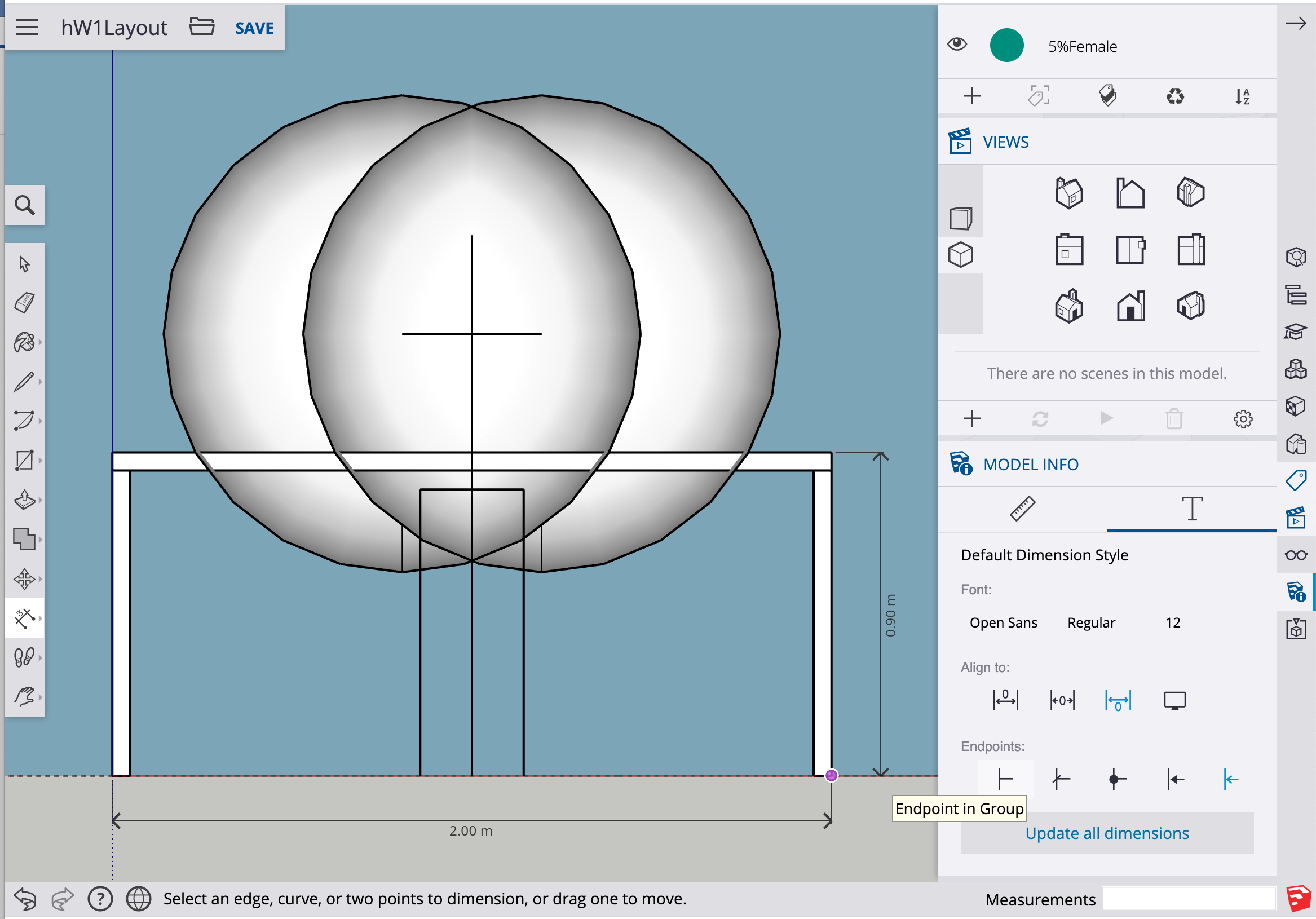
Layout view
Viewports
Dimensions
Section
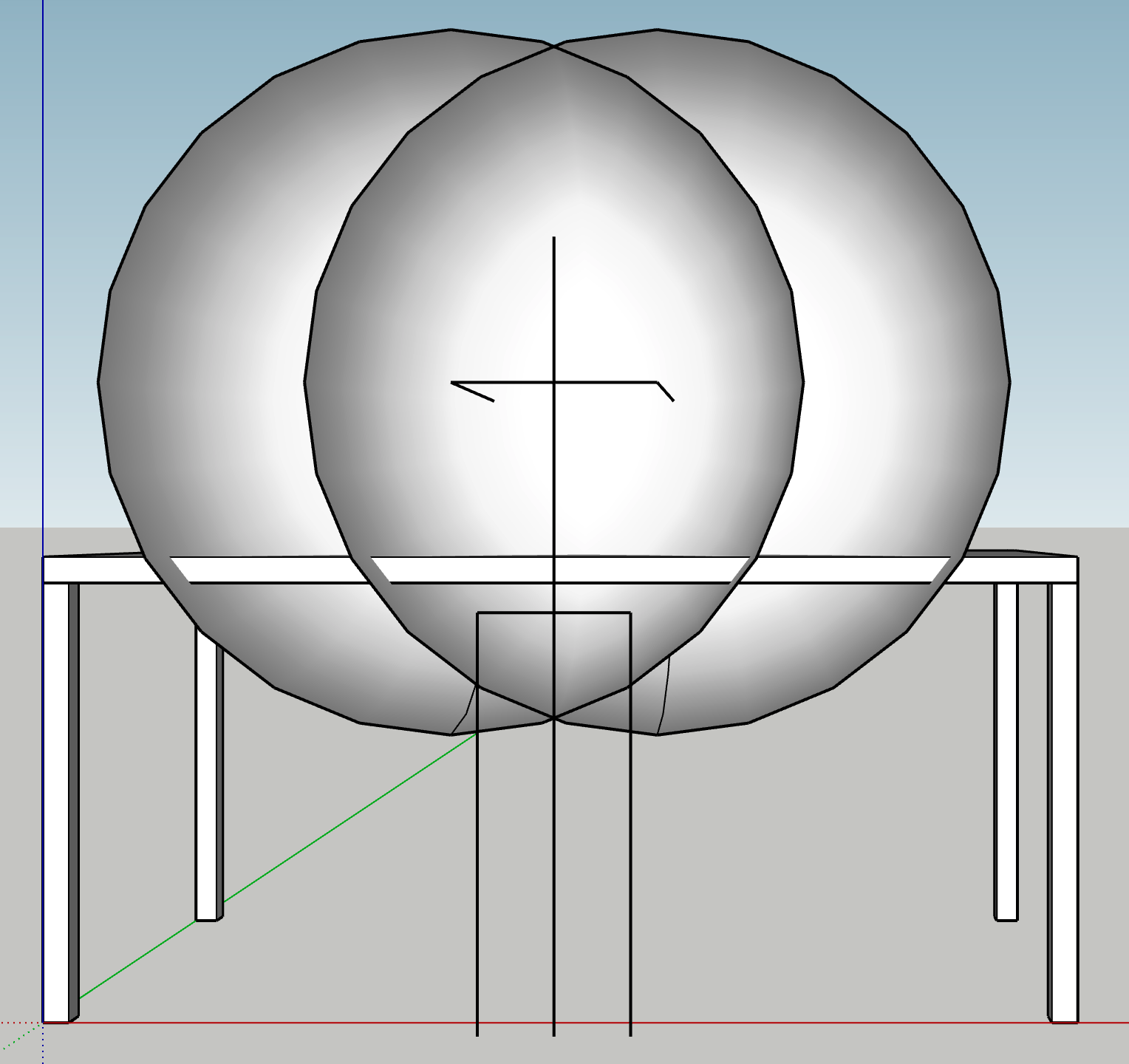
a
b
Figure 5: The buttons in the upper left corner of the view window switch the ortho views between "parallel," a, and "perspective" views, b.
(Use View cube to select front view.)