 |
Color Key Magenta = Baseline Orange = Shore Green = Bearings Red = Measured Angles Blue = Water |
Navigation: Near Shore Mapping- Adding Underwater Objects To the Contour
by
Larry "Harris" Taylor, Ph.D.
This material is copyrighted and all rights retained by the author. This article is made available as a service to the diving community by the author and may be distributed for any non-commercial or Not-For-Profit use.
All rights reserved.
This is a text-expanded version of the outline used in the contour mapping section of the author's navigation specialty class.
Go To: Home About "Harris" Articles Slides War Stories Editorials Links Fini
The Baseline Offset technique provides a fairly robust, low-tech method for compiling topographic information. Typically, once the bottom contour is established, the features of the local environment are added. Additions to the bottom contour are facilitated by referring to the already established baseline.
Using Angles
For surface features, the Pelorus can be used to quickly and conveniently establish angles from the baseline to an object to be located on the map/chart. This is done by recording the bearing (observed angle from reference baseline to object being located) from 2 different locations along the baseline to the object to be mapped. The points on the baseline chosen for the measurement should be well separated. Ideally, the intersecting lines will approximate a right angle (90o). Underwater objects can be located on the chart either by using surface buoys attached to the object being mapped or by measuring from an established underwater baseline. The line from object on the bottom to the surface should be taut, so the position of the surface marker accurately reflects the position of the underwater object being mapped. One way of doing this is with swim noodles, but any easily observed marker will do. Once the angles have been recorded, then the object being mapped is located at the intersection of lines drawn from the measured bearings.
|
Color Key Magenta = Baseline Orange = Shore Green = Bearings Red = Measured Angles Blue = Water |
A check on the accuracy of the angular measurement from the baseline to the mapped object would be to determine the bearings from the object being measured (at the intersection of the above green lines) to the baseline point of measurement. This is called a back-bearing or, for compasses, a reciprocal heading.
This technique can also be applied underwater to locate objects along a baseline or transect. In the absence of professional quality (i.e. expensive) survey tools, low cost recreational underwater lasers (typically these have 100 foot (33 meter) range of illumination with a depth limitation of approximately 100 fsw (33 meters)) can be added to common tools to generate reasonable devices for determining angles underwater. (Operational note: As with any dive light, care should be taken to avoid looking directly into or shining the laser beam directly at anyone's eyes since laser light may possibly damage eyesight.)
A goniometer is a device used by physiologists to measure the range of motion of various body joints. It is typically marked in one degree increments. By drilling a couple of holes in one arm (these tools are typically made of stainless steel and require a drill press to facilitate the drilling operation; using hand drills is definitely not recommended), a laser can be attached with spring clamps using a couple of washers and a locking nut (below, left). The modified goniometer then becomes a device for measuring angles in the underwater realm. One arm is placed along the baseline and the swivel is moved until the laser light is on the object being mapped. A close up of the angle measuring region (a protractor) is shown below right.


In the same fashion, a laser can be added to a carpenter's protractor. These are typically marked in 2 degree increments. In this case, long screws holding the spring clamps to the measuring device facilitate movement of the protractor arm. This modified carpenter's square is shown below. To determine the desired angle, one edge of the protractor is place along the baseline and the protractor arm is moved until the laser light point falls on the object being mapped. The bearing is then read from the scale.
 |
 |
|
Top |
Bottom |
With either of the above devices, the diver records a distance point on the baseline and angle at that point from the baseline to the mapped object. The distance and angle information can then be plotted (as in the above diagram for Pelorus measurements) to locate the mapped object on the map grid.
In practice, the laser is secured to the clips with a small polypropylene (black) tie wrap to ensure the laser stays attached to the device. Once the tie wrap is fastened, then the laser is turned on and checked to ensure the beam is projecting down the center of the degree measuring device.
The practical limitation of these devices is the power output of the laser and water clarity.
Using Distances
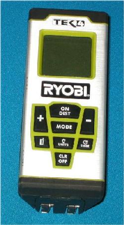
On the surface, professionals will use lasers and GPS devices coupled to an electronically integrated mapping data station to precisely determine position and distance. These are typically well beyond the price range of most recreational divers. However, for surface use at limited ranges (typically, maximum range 60 meters (195'), there are lower cost distance measuring lasers available from home improvement and hardware stores. One example is shown below.
At the non-professional (low-budget) level, surveyor's tape measures are used to locate objects relative to the reference baseline. Using 2 measured distances from a baseline is a very common and easily mastered technique for underwater surveys.
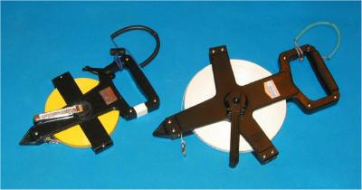
100 and 200 ft' Fiberglass Surveyor's Tape Measures
The diver records the distance between a point on the baseline and the object being measured. As with angles, it is best to record measurements from widely separated points.
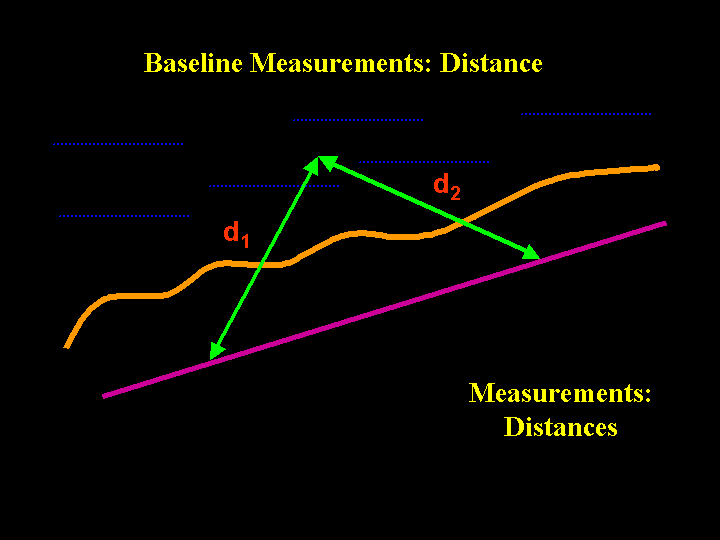 |
Color Key Magenta = Baseline Orange = Shore Green = Distances Blue = Water
|
To position the mapped object on the contour map, two arcs, one for each distance measured, are drawn on the map grid. The intersection of the two distances is the location of the mapped object. This is the most common technique found in underwater mapping using surveyors tapes.

While two points are sufficient to determine a position of a mapped object, more confidence in the reliability of the measured position can be done by measuring three times. Hopefully, each of the measurements with provide the same location for a mapped object on the map grid. However, particularly when three lines are used, the intersections typically do not exactly coincide. When this occurs, the point being measured is placed at the center of the uncertain area (sometimes termed the "region of uncertainty"). The process of using intersecting arcs or circles determined by either distance or angle measurements to locate an object on a reference grid is termed trilateration. The term is derived from the historical precedent of using three intersecting circles of position to determine the position of a vessel on the surface of the globe.
For most underwater surveys, given the size of the object being measured, compared to the scale of the final drawing, two measurements are sufficient. A third measurement is typical for vessels at sea or airborne aircraft to better estimate position on the surface of the globe during long duration travel.
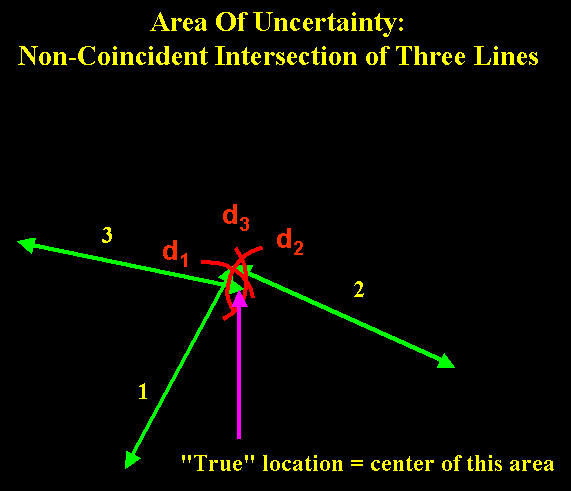 |
For measurements of distances
1, 2 and 3:
Plotted arcs d1, d2 and d3 intersect to form a "region of uncertainty" Point is plotted as the center of the "region of uncertainty" |
Some Math
The branch of mathematics that deals with shapes of objects is called geometry and the specific branch of geometry the describes triangles (three-sided objects) is called trigonometry. Historically, triangles have been used as a basis for surveying because with simple tools, the three sided shape provides consistent, reliable results for determining distances and angles. The combination of field measurements and trigonometry is used to locate objects on a map grid without having to make all possible measurements.
Sum of the Angles
In any triangle, the sum of the angles is always 180o. So, if you measure any two angles, the third angle can be determined by subtraction.
Example:
In our baseline measurements (see figure below), we determined that the two angles from baseline to the object being measured are respectively 48o and 42o.
Solving for the third angle:
Measured angles sum = 48o + 42o = 90o
Since the sum of the three angles is 180o , the third angle is found by subtraction: 180o - 90o = 90o.

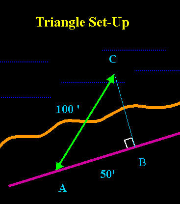
The Right Triangle
The easiest triangle to use is the right triangle. This is a triangle that contains one right (90o) angle. The right angle within a triangle is commonly designated by a small square (below, in white). The Greek philosopher, Pythagoras, is credited with the description of the mathematical relationship that describes the sides of a right triangle. His description, the Pythagorean Theorem, is that for any right triangle, the squares of the sides adjacent to the right angle (sides A and B, below) when summed, give the square of the side opposite of the right angle. The side opposite of the right angle (side C below) is called the hypotenuse. Mathematically, for distances of sides A, B, and C:
A2 + B2 = C2

The theorem is often stated as," the sum of the squares of the adjacent sides is equal to the square of the hypotenuse". So, knowing any two sides of a right triangle, the third side can be calculated. For the triangle above:

where ![]() is the mathematical symbol for square root
is the mathematical symbol for square root
Example:
For an underwater survey, using the diagram above, a diver determines the distance along the baseline is 30 feet. A line orthogonal (at right angles) from the baseline to a measured object is 40 feet. What is the distance along the hypotenuse?
Using the Pythagorean theorem: A2 + B2 = C2
Substituting known values: (30 ft)2 + (40 ft)2 = C2
Solving for C: C2 = 900 ft2 + 1600 ft2
C2 = 2500 ft2
C2 = ![]() 2500 ft2
2500 ft2
C = 50 ft
One easy to remember right triangle has sides of ratios of 3, 4 and 5. (Remember that the hypotenuse is always the longest side).
Ratios
For right triangles, two different ratios have been defined. Typically the corners of a triangle are labeled in capital letters, with small letters defining the side opposite of the capital letter as shown below.

For the triangle ABC (with corresponding sides of length a, b and c) defined above, there are two useful ratios:
sin = opposite / hypotenuse
cos = adjacent / hypotenuse
Example:
For the right triangle above with sides 3, 4 and 5, assume:
a = 3 units
b = 4 units
c = 5 units
Then
| sin A = a/c ==> 3 units / 5 units = 0.60 | sin B = b/c ==> 4 units / 5 units = 0.80 |
| cos A = b/c ==> 4 units / 5 units = 0.80 | cos B = a/c ==> 3 units / 5 units = 0.60 |
For 90o, the sin = 1.0 and the cos = 0.0
There are both digital and tabulated tables of sin and cosine values. Most modern calculators have these functions as built-in operations. These tables and functions allow calculation of distances and angles between mapped objects. Often, in software applications or surveying instruments, these formulas are transparent to the user. For example, in the baseline example above, because the measurements determined a right triangle was formed, we can use sin or cos values for measured angles to determine the unmeasured distances. This can save time in doing the actual measurements or survey, as well as serve as to serve as a check against the actual measured values, especially when first learning surveying techniques.

We measure side c, the hypotenuse, along the baseline with our fiberglass tape. If c= 64 feet, then
side b = opposite / hypotenuse = sin 42o
Substituting:
b / 64 ft = sin 42o
Rearranging:
b = 64 ft x sin 42o
Substituting:
b = 64 ft x (0.669)
b = 42.8 ft
For side a:
side a = opposite / hypotenuse = sin 48o
Substituting:
a / 64 ft = sin 48o
Rearranging:
a = 64 ft x sin 48o
Substituting:
a = 64 ft x (0.743)
a = 47.6 ft
The above solution, using the sin function, required measurement of one distance and two angles to determine the two unknown distances of the triangle. This is sometimes called the angle-side-angle method. It produces very reliable results.
In the above example, we can save another in-water measurement by determining only one angle; in this case at point B. So, we measure the distance (64 ft) along the baseline. As above, we use the sin function to determine side b, but then use the cosine function to determine the side a distance:
For side a:
side a = adjacent / hypotenuse = cos 42o
Substituting:
a / 64 ft = cos 42o
Rearranging:
a = 64 ft x cos 42o
Substituting:
a = 64 ft x (0.743)
a = 47.6 ft
Because the right triangle relationships are time-saving and simple to exploit, the right triangle is the basis for most surveying operations.
Non-Right Triangles
Some triangles are not right triangles, so the Pythagorean Theorem and the simple ratios above are not applicable. For these triangles, alternative procedures are necessary. In general, distance measurements, particularly underwater, are subject to the most error or uncertainty. So, it is common to minimize distance measurements and use the science of triangles, trigonometry, to determine non-measured distances.
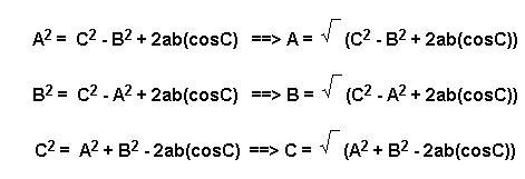
Law of Cosines
The law of cosines is an embellishment of the Pythagorean Theorem that accounts for the decrease in the size of the side corresponding to hypotenuse that occurs when a right triangle is distorted out of the right triangular shape. Mathematically, it is expressed as:
C2 = A2 + B2 - 2ab(cosC)

Solving:
where ![]() is the mathematical symbol for square root
is the mathematical symbol for square root
Since the value for the cosine of 90o is zero, the value of the expression 2ab(cosC) is zero for the right triangle. So, for a right triangle, the law of cosines becomes the Pythagorean Theorem.
Example: A diver measures on the baseline a distance of 46 feet. The angle to the observed object to be mapped is 36o with a distance of 22 feet.
Using the law of cosines to find distance c:
C2 = A2 + B2 - 2ab(cosC)
Substituting
C2 = (22 ft)2 + (46 ft)2 - 2 (22 ft x 46 ft) (0.809)
Multiplying values
C2 = 484 ft2 + 2116 ft2 - 1637 ft2
Combining terms
C2 = 963 ft2
Solving for c
C = ![]() 963
ft2
963
ft2
C = 31 ft
Law of Sines
Another application of trigonometry is called the law of sines. This can be applied to determine the length of the sides of a triangle if 2 sides and the angle opposite one of the known sides has been determined. Alternatively, it can be applied if two angles and the length of one side opposite a known angle is known. Mathematically, the law of sines is expressed as:
sin A /side a = sin B / side b = sin C /side c

Example: A diver has measured two angles from the baseline to the measured object. In addition, he has measured 2 distances. Determine the length of the third side.

Using the law of sines:
sin A /side a = sin B / side b = sin C /side c
Substituting for all
sin32 / 22 ft = sinB / 46 = sin 36/ c
Choose the relationship that leaves only one unknown (the side to be calculated)
sin32 / 22 ft = sin 36/ c
Substitute sin values
0.530 / 22 ft = 0.58 / c
Solving for c
0.530 / 22 ft = 0.58 / c
0.024 /ft = 0.58 / c
c = 0.58 /0.024 ft
c = 24.2 ft
The 1:2: Radical 3 Triangle
Assume we want to determine an approximate operational guideline for the distance off the baseline our recreational laser would support given excellent visibility (i.e. Assume the manufacturer's guideline of 100' visibility for the laser beam is the defining limit of measurement). Although one way would be to swim in the water off the baseline until the light was not visible, a reasonable estimate can be made without getting into the water. Assuming the hypotenuse of the triangle represents the 100 foot visibility limit between observer on the baseline and the object being measured, we can use the well-remembered ratio of 1: 2: radical 3 to set up the following:
Whenever the hypotenuse
of a right triangle is twice one side of the triangle, the remaining side with
be the adjacent side times the square root of 3 (radical three, or 1.732). So,
here the blue line that represents a reasonable working limit for working off
the baseline will be 50 ' x ![]() 3
= 86.6'.
3
= 86.6'.
Check using the Pythagorean Theorem:
Solving for the blue line:
a2 + b2 =c 2
Substituting:
a2 + (50')2 = (100') 2
Rearranging:
a2 = (100') 2 - (50')2
a2 = (10000 ft2) - (2500 ft2)
a2 = (7500 ft2)
a = ![]() (7500
ft2)
(7500
ft2)
a = 86.6 ft
So, a theoretical maximum guideline for surveys using recreational lasers of 100 visibility is about 86 feet off the baseline. Of course, the actual working limit will be dependent upon the water clarity, ambient light, and amount of silt generated by the divers on the survey team. For example, in early tests in a swimming pool with the lights out, the limit of visibility of the laser dot was 57 feet , but in open water on a bright, sunny day, it was difficult to resolve the red laser light dot beyond about 10 feet.
The 1: 2 : ![]() 3
triangle is easily constructed and, as such, is commonly used in field survey
work.
3
triangle is easily constructed and, as such, is commonly used in field survey
work.
Conclusion
Simple tools and a trigonometry can be used to locate surface and underwater objects on established map contours. The tools on hand, the nature of the objects being measured, the bottom contour, the number of divers, and the ease of determining various measurements will determine which trigonometry relationships will be most useful. However, a lit bit of math will save enormous amounts of time needed to compile enough measurements to locate objects on a contour map.
Acknowledgement
Thanks to Richard Griggs for technical assistance in modifying the devices.
Calculations were done on a HP 15C handheld scientific calculator.
Go To: Home About "Harris" Articles Slides War Stories Editorials Links Fini
About
The Author:
Larry
"Harris" Taylor, Ph.D. is a biochemist and Diving Safety Coordinator
at the University of Michigan. He has authored more than 200 scuba related
articles. His personal dive library (See Alert Diver, Mar/Apr, 1997, p. 54) is
considered one of the best recreational sources of information In North America.
All rights reserved
Use of these articles for personal or organizational profit is specifically denied.
These articles may be used for not-for-profit diving education