Navigation: A Near Shore Mapping Exercise
by
Larry "Harris" Taylor, Ph.D.
This material is copyrighted and all rights retained by the author. This article is made available as a service to the diving community by the author and may be distributed for any non-commercial or Not-For-Profit use.
All rights reserved.
This is a text-expanded version of the outline used in the contour mapping section of the author's navigation specialty class.
Go To: Home About "Harris" Articles Slides War Stories Editorials Links Fini
Jump To: Method Equipment Process Data Sheet Maps
The Baseline Offset Mapping Method
Maps are simply physical representations of some geographic location. All maps must be made from a set of spatial coordinates or measurements. They can be as simple as a couple of quick squiggly lines drawn on the back of a napkin, or as complex as multi-colored holographic three-dimensional images downloaded from a GPS satellite that provide a real-time scrolling profile of location and elevation. Maps provide specific information on distance, direction, elevations (depths), and key landmarks. In general, the more data points used to generate the map, the better the quality of the map's correspondence between the map image and the represented geography. It is the user that determines the needs of the map to be used and the resolution (scale) of the map that is needed. For example, a sailor plotting direction between the UK and the US while crossing the Atlantic Ocean does not need the chart to be as finely detailed as a sailor trying to avoid a reef while entering a local harbor.
This class will use a simple technique that can be used with a variety of common materials, to prepare a bottom contour profile (or near shore survey) of a section on an inland lake beach.
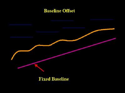
The technique we will use is called the baseline offset. It is simple, yet provides reliable, reproducible results and can be done with a minimum investment in equipment. It is the most frequently employed (in the absence of electronics) in-the-field mapping method. The term baseline offset means that all measurements used to determine the map coordinates will be made using a fixed straight line as a reference.
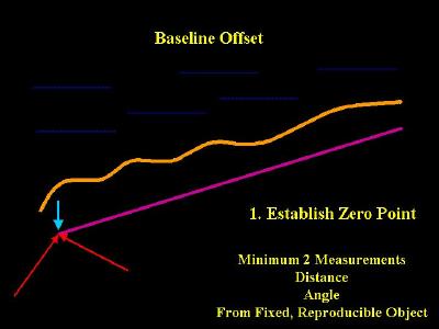
The baseline is a long, straight line that is established on a beach or underwater site (see figure, below left). It is the invariant standard from which all measurements are based. IT MUST BE IMMOVABLE. Typically, the line is established from a single point, called the zero point. The zero point (origin) is some physical point in space whose position can be recreated at any future time for reproducible measurements (see below, right). Typically, it is established by measuring two distinctly different distances and angles from fixed objects (as from the two x points in the diagrams below) to the zero point. From the zero point, a straight line parallel to the mapping site is drawn. The location of the zero point and the length and direction of the baseline from the zero point provides a reproducible means of establishing a consistent reference.
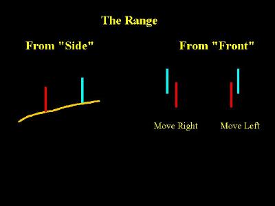
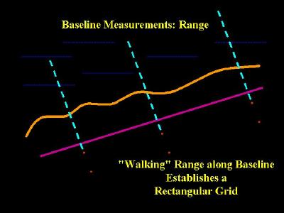
Once the reference baseline is established, a range (two poles or markers of different heights used to establish a line-of-sight, below left) is used to establish an offset line. Ranges (typically large triangles) are often used by vessels as navigational aids to allow vessels to get into the proper alignment to enter a channel or a turn. As long as the components of a range are superimposed, then the diver (or vessel) is somewhere along the offset line. Depth measurements are taken at 10 foot increments along the established offset line.
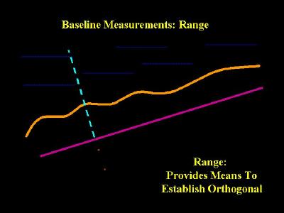
The bottom contour map is assembled from depth measurements made at fixed distance increments along a line (the offset) perpendicular to this reference baseline. The greater the number of measurements, the more closely the generated map will trace the locale being examined. Measurements are then made at fixed intervals (like every 10 feet, depending on accuracy needed) along the offset line to some pre-determined limit. Once the measurements along one offset line are done, the range is moved, another offset line is established and more measurements are made. So, this technique of mapping is really a process of "walking" multiple offsets down the baseline and recording the measured data.
Once the bottom contour is determined, then objects can be placed within the map grid. For objects visible on the surface, the Pelorus can used to provide relative bearings from two (or more) points along the baseline (see figure, below left). Large underwater objects can be located on the surface via diver-deployed marker buoys. A more detailed summary of plotting techniques for adding objects to a contour map or grid can be found here.
The baseline offset technique using ranges, rather than underwater swimming with a compass, can also be used to lay transect lines along a bottom contour for assessing objects in a near-shore environment. This technique eliminates diver navigational errors from poor technique, currents, or submerged metallic objects that would alter a compass heading. In this case, the diver swims on the surface with a measured line. After using the range poles to assure that the position is at right angles to the designated range, a marker buoy can be dropped to identify the position on the bottom. Later, divers can run transect lines from the shore baseline to the appropriate marker buoy. After a series of lines extending out from shore is established, each separate line from shore becomes a secondary baseline and using trilateration (determining position from 2 measurements, above right) bottom objects or artifacts can be plotted relative to the underwater lines.
The Equipment
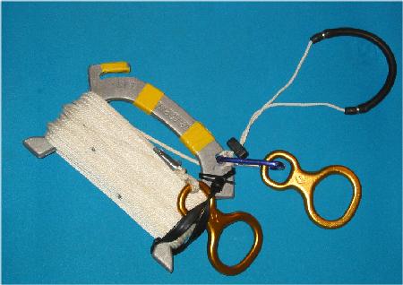
The baseline is simply a standard divers 1/8" 100 foot line wound around a handle (below, left), drawn taut and anchored. We have found screw drivers to be excellent stakes for surface use. (Underwater, we secure the baseline with the same rods we use as ranges, see below). We use a 2 pound (12" handle) sledge hammer to drive both stakes and range rods into the ground. This size hammer works well underwater, as well as on the surface. We use the same line underwater and on the surface.
All our lines are marked using an "approximate" distance code. The taut line is laid next to a surveyor's tape and marked every 1 foot ... a short mark on the foot increment, a longer mark every 5 feet, a still longer mark every 10 feet and one very long mark at 50 foot. For example, the line marking for 77 feet on the line is shown below, right.
Although we originally used standard diver's clips to attach the lines to our baseline, this sometimes posed a problem underwater with the 1/2" aluminum rods (most clips would not encircle the rod), especially in limited visibility or in current situations. So, we changed to using yellow (for visibility) climber's figure-eights as our securing points. The free end figure eight is the initial anchoring point. Underwater, we simply place the aluminum rod baseline pole through the figure eight and drive the long aluminum rod into the the ground using a 2-pound short-handled sledge hammer. The long rods provide a point for attaching unused gear (like the sledge hammer at the end of the line), strobe lights, or other equipment, as well as providing a long length to ensure the line is securely fastened to the bottom. The line is then unwound (while keeping the line taut) until the line is totally deployed ... the figure eight secured to the handle with a non-climbing carabineer is then secured with the second aluminum rod. This arrangement provides a quickly assembled (and removed), secure baseline for searching or mapping operations. If the line will be used for more accurate measurements, as in using trilateration on a shipwreck, a surveyors tape can be attached to the poles. Underwater, we finish the line by attaching small floats (see Swim Noodles as Dive Markers). to ensure that the established line can be found for multiple dive operations.
Lastly, to keep the free line end figure eight secure during transport, we added a small elastic band ... the figure eight is slid under this band while carrying and when used, the figure eight under the band becomes the initial point of the line.
 |
 |
|
The "baseline" |
The markings: bottom line is 77 feet |
The original distances from the fixed, known objects to establish the zero point is determined using a 100 foot surveyors tape; the direction is noted using a "gun-sight" compass. (We prefer a "gun-sight" (hand-bearing) compass marked at every degree, as opposed to a diver's compass that is only marked every 5 degrees.)
The range rods are 4 to 6 foot long 1/2" diameter aluminum rods. (They must be of different heights for the in-water diver to discern their position.) I have added colored/reflective stripping every foot along the rods to increase underwater or at-night visibility, but that is not necessary for this application. In addition, a piece of tightly fitting hose on the rod will provide a hand-hold that is useful when pounding the rod into the ground. Finally, since these rods may be left alone on a beach at night (with lights, to mark the exit point) or used in other underwater training exercises, I have added a laminated business card to each rod with a notice on the back side of the card that indicates these rods are in-use by divers. Two different sets of rods facilitate mapping in that one set can be established while the other is being used. This minimizes the wait of the diver in the water when changing offsets. Typically, a diver reads one offset moving out away from the beach and the next offset moving in towards the beach.
The Range Rods
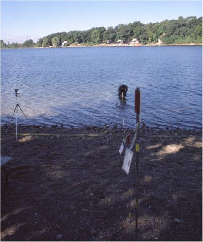
Once the baseline (a diver's 100 ft line) is staked out, a 100 foot surveyors tape is laid directly along side the baseline. We use a diver's line (easier to maintain its position in the ground, especially if the ground is hard) as the baseline, but our measurements are taken by the distance markings on the surveyor's tape. (We align the zero marks on both tapes). This is the basis for all the map measurements that will be made. In class, we typically measure every ten feet. This provides enough information (100 foot by100 foot section of the beach, plus the distance from the baseline to the waterline for a total of 121 data points) to give a reasonable representation of the bottom contour along the measured section of the beach. Although a diver's compass could be used to determine the direction of the offset line, we prefer to use a non-magnetic device, a sighting circle (or Pelorus). The sighting circle, (mounted on a small photographer's tripod with a weighted line hanging down from the center of the sighting circle to ensure the center of the sighting circle is directly over the point of measurement on the surveyor's tape), is lined up to point directly along the baseline. Then, the circle is simply rotated 90 degrees to give the bearing needed for the offset line. The "surveyor" uses the sight of the sighting circle to instruct the assistant as to where to place the range rods. The sighting circle provides a rapid, reliable means of insuring that the range rods are located perpendicular to the base line.
 |
 |
| Surface Baseline Implements | "Gun-sight" Compass & Sighting Circle (Pelorus) |
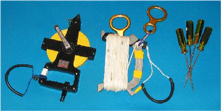
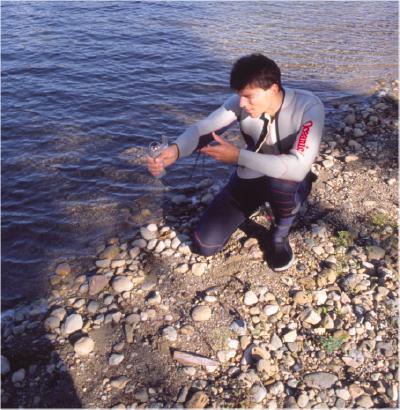
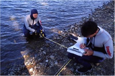
The diver in the water uses the range poles to establish that measurements are being made along the chosen offset line. The diver unreels a surveyors tape (fixed at the baseline) to establish distance along the offset line from the baseline on the beach and every 10 feet, stops to take a depth reading. Since this is an exercise, the depth is determined both by plumb bob (a thin line with a small weight attached, marked every foot) and a hand held sonar device. Note that all tools used in-water have lanyards attached to assist the diver in maintaining possession of the tool. (First law of in-water work is always return from a dive with the same amount (or more) of equipment that you had when you entered the water.)
In-water tools
There are 4 different tasks involved and typically each student does each task for 2 or 3 offsets ( A 100 foot line, marked at 10 foot intervals has 11 offsets). The tasks are
1. In-water diver: measures distance from baseline and measures depth at every 10 feet. Typically, the depth readings on the first offset are measured with a weighted line, the rest with the sonar.
2. Recorder: monitors diver and records measurements as made.
3. Surveyor: uses sighting circle to determine offset line bearing; instructs assistant in location of the rods to establish the range.
4. Assistant: pounds the two range poles into the ground under direction of surveyor Also, moves the diver's measuring tape from one offset to the next during change-over.
I typically allow each group to determine their own "working rhythm" (i.e. when sighting circle & poles are moved, the order of tasks done, the work pace, etc.) Mapping a 100 x100 foot section of beach in this manner takes approximately 2 hours.
|
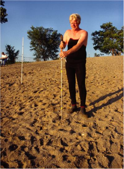
Using Hand Bearing Compass to establish baseline |
Setting surveyor's tape to establish reference |
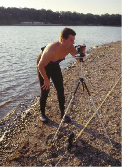
| Using Sighting Circle to establish range |
| After range is established, first measure to waterline |
| Then, "walk the offset" down the baseline and measure depth at 10 foot increments perpendicular to the range |
| Record all data as it is collected |
The above describes the best case scenario: surface control of all activities, surface measurements on a relatively calm body of water. Other locations may require modification. For example, running surface tapes as offsets may not be viable in an active surf zone, a cliff face, or rapidly moving water. This method also presumes a beach is present. Obviously, different circumstances require modification of the above. However, the general principles will still hold, their implementation will simply be less desirable and perhaps, as such, less accurate. In place of a surface tape, divers can use an underwater reel (used in cave or wreck diving) and reel out a marked line along a compass heading. At each measurement point, the depth (on diver's depth gauge) can be marked on a slate. Modifications will vary depending on local environment, equipment on hand and number of people available to dive.
The Data Sheet
Having a prepared data sheet speeds up the process and ensures that all the needed data are collected. This is our sheet. (WL=Waterline)
Some Student Maps
Students were told to plot the depth/distance data in a manner that would be useful for their needs. The results I receive are typically in one of four different formats.
Hand-Drawn
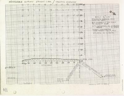
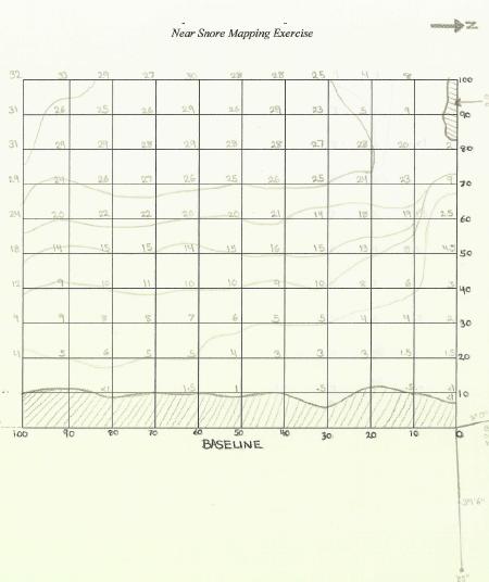
Figure 1 is a contour map that simply displays the raw data of depth in feet at each data point collected. This plot also shows the zero point determination.
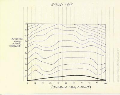
Figure 2 is the most common form of data representation: similar depths are connected by a line to show a depth contour
Figure 3 is a plot of one specific offset's depth profile; there is one such profile for each of the offsets measured
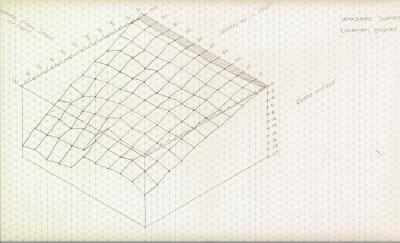
Figure 4 is a plot of the data on three-dimensional graphing paper.
The text on the figures is difficult to read; the figures have been severely reduced to lessen bandwidth. However, the resolution should be sufficient to demonstrate the type of curve represented.
|
Figure 1 |
Figure 2 |
|
Figure 3 |
Figure 4 |
Machine Assisted
Today's world offers a variety of software applications ranging in features (and price) from the simple to the sophisticated.
Figure 5 used a word processor for the data presentation
Figure 6 is 3 D contour plot from a professional mapping software application.
 |
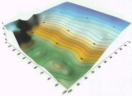 |
| Figure 5 | Figure 6 |
Conclusion
The baseline offset method is a viable technique for divers to use. Remember that the quality of the finished map is directly related to the number of reproducible data points collected. The best way to ensure good data point collection is with a systematic grid using a fixed, reproducible origin.
Further Reading:
Somers, L. Near-shore Hydrographic Survey Using Divers, Michigan Sea Grant, 1987, 45 pages
Adding Objects to the underwater contours
Jump To: Method Equipment Process Data Sheet Maps
Go To: Home About "Harris" Articles Slides War Stories Editorials Links Fini
About
The Author:
Larry
"Harris" Taylor, Ph.D. is a biochemist and Diving Safety Coordinator
at the University of Michigan. He has authored more than 200 scuba related
articles. His personal dive library (See Alert Diver, Mar/Apr, 1997, p. 54) is
considered one of the best recreational sources of information In North America.
All rights reserved
Use of these articles for personal or organizational profit is specifically denied.
These articles may be used for not-for-profit diving education