|
University of Michigan
Joseph Paul
japaul@umich.edu
This summer, I worked in the SNAP (SuperNova/Acceleration Probe) project under the supervision of Professor Wolfgang Lorenzon as a part of the Summer 2003 REU Program at the University of Michigan. Most of my work was centered on developing a software package using LabVIEW for NIR sensor testing.
What is SNAP?
SNAP is a space-based telescope to study the expansion of the universe through distance-redshift relation of supernovae, currently planned to be launched in 2010. SNAP is expected to find and analyze over 2000 supernovae per year to study the nature of the dark energy.
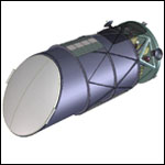 | |
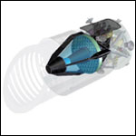 | An outer-view of SNAP | | An inner-view of SNAP | Wavelength coverage of SNAP is between 0.35 - 1.7 microns, which covers both the visible and the NIR (Near-Infrared) spectrum. The Michigan group is responsible for carrying out the tests for 36 NIR sensors which will mounted on the SNAP.
The NIR Sensors
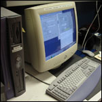
NIR sensors work essentially the same way as how CCD's work (method widely used by most digital cameras for capturing images). Each of the NIR sensors, made of semiconductors (HgCdTe), are sensitive to photons. These sensors are attached to a device called a MUX (Multiplexer). Each of the MUX are composed of 2048 x 2048 array of pixels. The signal which comes out of the MUX is sent to a PC which appears as an image on the screen.
My task was to create a software using LabVIEW to read out the signals from the MUX, and save them as FITS (an image format widely used in astronomy) files on a PC. The software development was done under Linux.
Developing the NIR Software
The processes required for communicating with the MUX from a PC can be summarized as follows: First, PC must send the assembler code onto the timing board through the PCI card. A DSP (digital signal processor) is located on the timing board, and this converts the digital signal from the PC to analog signal. The analog signal is sent to the MUX, which then starts the exposure process. The read out from the MUX is sent back to the timing board, and converted back into digital signal, and then back to the PC through the PCI card.
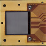 |  |
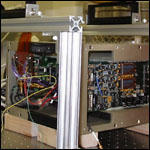 | |
 | MUX | | Timing Board (DSP) | | PC | So communication with the MUX and the timing board can be achieved only after the connection with the PCI card is established. The Linux version of LabVIEW does not support low level system device driver calls, so LabVIEW cannot talk to the PCI card directly. However, communication with the PCI device can be done in C by calling the PCI device driver entry points (functions). So it was necessary to write a collection of C library files, containing functions for sending specific commands to the PCI card, which are then called from LabVIEW.
Works Accomplished
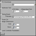
I was able to write all the necessary components of the C library files and the program in LabVIEW so that I can save the images from the MUX on the PC as FITS files. I also wrote a
document describing how to communicate with the PCI card in C / LabVIEW.
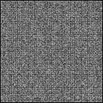 | |
 | First readout from the MUX | | |