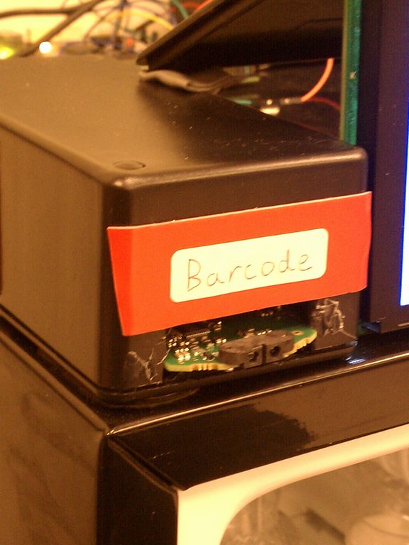
The purpose of the barcode scanner is to scan items (one time only) after they are
purchased to obtain each item's barcode data. This data is then used in an online search to
obtain the product's identity and nutritional information; this information is then stored in our
system's database. The high-level operation of this device is to generate an interrupt after
a UPC-A barcode has been scanned and data is ready for processing. There were several
challenges involved with this task, from determining the device's data communications protocol
to implementing a low-pass filter for signal conditioning and proper functionality. There were
several key components that were necessary for the integration of the barcode scanner with our
system:
* CoreUARTapb serial communication controller
* MAX232N level converter
* Low-Pass Filter (220uF capacitor & 10 Ohm resistor)
RFID Fridge
A smart refrigerator for the home
The first step was to read the scanner's documentation and determine the communication protocol it uses. The barcode scanner adheres to the RS232 standard for signal voltages, timing, and functionality. It communicates data serially via a 9-pin DTE-to-DCE cable. I utilized two of the signals for our system's purpose: Transmit Data (TxD) and Request to Send (RTS). The latter was used for interrupt generation. The next step was to implement hardware in Libero that could serve as an interface between our application and the barcode scanner. This was accomplished with a CoreUARTapb serial communication controller, which serves as a UART device and APB bus wrapper. When a barcode is scanned, the data is transmitted serially to the CoreUARTapb's FIFO receiver buffer via the TxD line and waits for processing. After the data has been transmitted, the RTS line goes high and this signal triggers an interrupt. The processor jumps to the interrupt service routine where it stores the barcode data in a char array via a call to UART_get_rx().
Proper configuration of the barcode scanner was required before it could function properly. Using the configuration manual, the scanner was set to operate with the following parameters: baud rate of 9600, 8 data bits, and no parity bits. After configuring the barcode scanner, I still noticed that data was not being sent (using the logic analyzer to debug). To fix this problem, I had to disable the "Wait for CTS" setting which was preventing data from being sent until receiving a CTS handshaking signal.
Two more pieces of hardware were required for proper functionality, the MAX232N level converter and a low-pass filter. The level converter was used to bring the RS232 standard +-12V signals coming from the barcode scanner down to a safe 0-5V range that the UART hardware requires. After this device was used (for both the TxD and RTS lines), I began to notice that the interrupt line wasn't functioning as intended; it was generating multiple interrupts per scan, rather than just one. I used the logic analyzer and oscilloscope to determine the problem and noticed significant crosstalk between the TxD and RTS lines. The noise generated on the RTS line due to the transmitted data on the TxD line was not an issue when the signals were +-12V. After the level conversion, however, the noise was significant enough that it was being interpreted as logical highs and lows on the logic analyzer. This was causing several interrupts, rather than one after all the data has been transmitted. To fix this problem, I implemented a low-pass filter which would block these high frequency pulses from passing through to the processor. After conditioning the RTS line through this low-pass filter, the signal was functioning as intended.
