Central Campus Air Quality Model (CCAQM) Instructions
·
Link Geometry
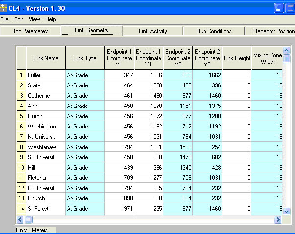
o Link
Name
- Optional. The user may define a 12-character description for the
link.
o Link
Type
- The user must select one of the following 5 choices to define the
type of roadway that each link represents. (Click a cell in this
column to view a drop list and select from the following 5 options.)
§ At-Grade
- For at-grade sections, CALINE does not permit the plume to mix
below ground level, which is assumed to be at a height of zero. The
height of the link above the ground is defined in the Link Height
cell.
§ Fill
- For fill sections, CALINE4 automatically resets the link height to
zero, and assumes that air flow follows the surface terrain,
undisturbed. This choice is functionally no different than the
At-Grade choice with a link height defined as zero. If you wish to
model a link that is slightly elevated above ground, the At-Grade
choice is more appropriate.
§
Depressed - For depressed sections, CALINE4 increases the residence
time of an air parcel in the mixing zone. The residence time
increases in relation to the depth of the roadway depression.
(Mixing zone = width of traffic lane(s) plus 3 meters on each
side.) In such a case, CO concentrations adjacent to the mixing
zone are higher than those for an equivalent at-grade or fill
section. CO concentration drops more rapidly downwind of a
depressed link because vertical mixing increases with residence
time.
§ Bridge
- For bridge sections, CALINE4 allows air to flow above and below
the link. The plume is permitted to mix downward from the link,
until it reaches the distance defined in the Link Height cell.
§ Parking
Lot - Parking lot links should be defined to be coincident with the
parking lot access ways. The CALINE4 algorithms adjust to account
for the reduced mechanical and thermal turbulence anticipated from
slow-moving, cold-start vehicles.
o
Link
Coordinates
- Links are defined as straight-line segments. The entire length of
each link should deviate no further than 3 meters from the
centerline of the actual roadway. The endpoint coordinates, (x1, y1)
and (x2, y2), define the positions of link endpoints. The user must
define the link geometry and receptor positions with a consistent
Cartesian coordinate system. The position of the coordinate system
origin is arbitrary and at the user's discretion. The y-axis should
be oriented north-south, with values increasing in the northward
direction. The x-axis should be oriented east-west, with values
increasing in the eastward direction.
o Link
Height
- For all link types except bridges, Link Height represents the
height of the link above the surrounding terrain. Ground level is
defined at 0 meters or feet (z=0). The units of measure (feet or
meters) are user-specified on the Job Parameters Page. For at-grade
links, the link height may be defined as 0 or a positive value. For
fill links, CALINE4 always treats the link as though its height was
zero. For depressed links, the depth of the depression should be
indicated as a negative value. For parking lots, the link height
should be defined as zero. For bridges, Link Height defines the
height of the bridge above the surface beneath it (a positive
value), while the link itself is considered to be at z=0.
o Mixing
Zone Width
- Defined as the width of the roadway, plus 3 meters on either
side. The minimum allowable value is 10 meters.
o Canyon/Bluff
Mix
- users should leave the Canyon/Bluff input values set to zero,
which disables the feature, since it is not applicable.
|