|
|
|
|
|
|
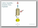
Liquid Propellant Rocket
Engine
Click the picture to open a new gallery. |
Back to Projects
Main Page | Back to my
Home
Page
| Liquid Propellant Rocket Engine Images | |||
 |
Introduction
This report describes the design of a static firing stand & a liquid rocket engine and the selection of the appropriate associated units. It is a shorter version of the report I prepared for the AERO 535 course, taken in the Winter 2004 semester. Before a rocket engine flies in its final application a considerable amount of developmental & proof testing is performed. The developmental & proof testing are performed on static firing stands which are equipped to make numerous measurements of pressure, temperature, flow, thrust, etc. necessary to define & diagnose rocket engine operation.
The firing stand discussed below is based on an Astrosystems’ Labroc VI laboratory equipment. The console of the current project is self contained & portable with the exception of requiring electrical power and a source of cooling water. The firing circuits & instrumentation can be controlled from a central computer. The design satisfies the following requirements set forth initially for the project.
Propellants – Methane (CH4) & Oxygen (O2).
An industrial gas supplier “B.O.C. Gases” was selected for the propellants. They had experience supplying Methane, Oxygen & Nitrogen (for purging the apparatus, after the completion of the test) for industrial applications. The specifications of the gases used are given below:
Methane –
Purified Grade 2 (99% pure)
Contents – 356 ft3 (9.87m3) @ NTP
Supply pressure – 2400 psig @ 70 °F
BHS 4 High Pressure Piston Regulator
Omega Instruments Model FD614 Portable Ultrasonic Flowmeter
Series 7510 Inline Filter - 10 Microns
Oxygen –
Extra Dry Grade 2.6 (99.6% pure)
Contents – 337 ft3 (9.42m3) @ NTP
Supply pressure – 2640 psig @ 70 °F
BHS 4 High Pressure Piston Regulator
Omega Instruments Model FD614 Portable Ultrasonic Flowmeter
Series 7510 Inline Filter - 10 Microns
Nitrogen –
Contents – 304 ft3 (8.51m3) @ NTP
Supply pressure – 2640 psig @ 70 °F
BHS 4 High Pressure Piston Regulator
Omega Instruments Model FD614 Portable Ultrasonic Flowmeter
Series 7520 Inline Filter - 10 Microns
Mass Flow of Propellants – 2.5 – 7.5 gms/sec.
The flowmeters specified above gave the required mass flow of the propellants. They had the following features & specifications:
Battery Operated
Non-invasive clamp-on transducer
Microprocessor based Signal Conditioning Electronics
Large character display
Flow range: 0.30 to 30.0 FPS (0.10 to 9.0 MPS)
Display: Single line – four digit LCD layout
Temperature: -28 °F to 140 °F (-20 °C to 60 °C)
Accuracy: ± 2% full scale
Thrust < 4 lbf.
The Gordon & McBride program was used to calculate the Coefficient of Thrust, Cf, which was used to calculate the thrust which was found to be approximately equal to 4lbf.
For a Chamber Pressure, Pc = 50 psia
Area at throat, At = 0.0147 in2
Maximum Cfmax = 1.2801
Minimum Cfmin = 0.7302
Maximum Thrust, Fmax = Cfmax x At x Pc = 0.8904 lbf
Minimum Thrust, Fmin = Cfmin x At x Pc = 0.5367 lbf
For a Chamber Pressure, Pc = 100 psia
Area at throat, At = 0.0147 in2
Maximum Cfmax = 1.4358
Minimum Cfmin = 1.0154
Maximum Thrust, Fmax = Cfmax x At x Pc = 2.1106 lbf
Minimum Thrust, Fmin = Cfmin x At x Pc = 1.4926 lbf
For a Chamber Pressure, Pc = 150 psia
Area at throat, At = 0.0147 in2
Maximum Cfmax = 1.5147
Minimum Cfmin = 1.1392
Maximum Thrust, Fmax = Cfmax x At x Pc = 3.3400 lbf
Minimum Thrust, Fmin = Cfmin x At x Pc = 2.5120 lbf
For a Chamber Pressure, Pc = 200 psia
Area at throat, At = 0.0147 in2
Maximum Cfmax = 1.5662
Minimum Cfmin = 1.2118
Maximum Thrust, Fmax = Cfmax x At x Pc = 4.6050 lbf
Minimum Thrust, Fmin = Cfmin x At x Pc = 3.5626 lbf
Chamber Pressure < 200 lbf/in2.
The calculations were done for 4 different chamber pressures – 50 psia, 100 psia, 150 psia & 200 psia. A model DGP8000 general purpose digital pressure gauge from Omega Instruments was selected for measuring the chamber pressure. An insulating material was needed between the pressure port & the gauge since inexpensive commercial pressure gauges were not certified for operating at temperatures greater than 140 °F. The gauge had the following features & specifications:
¼ ” Full Scale Terminal Point Accuracy
4 digit display with ½” high digits
Backlight feature for enhanced visibility
User selectable engineering units
Maximum pressure indication
Stainless steel wetted parts
Range: vacuum to 9999psi
Operating Temperature: 14 °F to 140 °F (-10 °C to 60 °C)
Mixture Ratio – 2 to 3.5.
The calculations were done for 16 different oxidizer / fuel ratios. (2.0,2.1,2.2,2.3,2.4,2.5,2.6,2.7,2.8,2.9,3.0,3.1,3.2,3.3,3.4,3.5).The flowmeters specified above could be calibrated to deliver the gases at the required oxidizer / fuel ratios. The supplier offered the option of many standard & custom direct reading scales, which could be selected for our application.
Area Ratio.
3 different area ratios were considered.
A converging nozzle was designed which could simulate the under-expanded case, which resulted when the nozzle exit pressure was higher than the local atmospheric pressure. The expansion of the fluid would be incomplete within the nozzle. This could happen at very high altitudes in an actual fixed – geometry nozzle.
A converging – diverging nozzle was designed which could simulate the perfectly - expanded case, which resulted when the nozzle exit pressure was equal to the local atmospheric pressure. To select a perfectly expanding nozzle, 64 different area ratios were considered. The area ratio that gave a perfectly expanded nozzle varied with changes in the combustion chamber pressure & oxidizer / fuel ratio. Hence the area ratio giving the highest specific impulse, Isp was chosen for the perfectly expanding nozzle design. The area ratio was 2.9288 at a chamber pressure of 200 psia & an oxidizer / fuel ratio of 2.7, giving an Isp of 258.28 sec.
A converging – diverging nozzle was designed which could simulate the over-expanded case, which resulted when the nozzle exit pressure was lower than the local atmospheric pressure because the exit area was too large. Another 64 different area ratios were considered and area ratio of 7.1 was selected for this purpose. A higher area ratio could be selected but it could result in separation of the flow in the diverging section of the nozzle. This particular area ratio assured that the nozzle is always over-expanded in the range of chamber pressures & oxidizer / fuel ratios considered.
Appropriate safety measures were considered for the design of the rocket & test apparatus.
Safety features in the rocket included circuits that prevented the spark plug from igniting if the coolant – water pressure was lower than the design value of 70 psia. Another circuit would initiate shut down of the system if the water pressure dropped below the design value, while in operation or if the chamber pressure fell below 50 psia. After each normal & emergency shut down, the entire rocket engine would be purged with gaseous nitrogen for 10 seconds. To prevent over exposure of personnel to toxic exhaust products, especially Carbon Monoxide, a wet scrubber was designed with a venturi of circular cross – section using heated tap water. This was later abandoned because of the limited solubility of Carbon Monoxide in water. The exhaust in the final design was routed through a duct to the atmosphere. The safety features in the test stand include restraints to prevent shifting of the cylinders, while in use and flexible braided hoses.
As required, the only fabricated components were the rocket engine parts. Suppliers were contacted for most of the standard components & systems used in this project.