|
|
|
|
|
|
Human
Powered Helicopter
Click the picture to open a new gallery. |
Back to Projects
Main Page | Back to my
Home
Page
| Human Powered Helicopter - Mechanical Drive Train - Images | Human Powered Helicopter - Electric Drive Train - Images | ||
 |
 |
I joined the Human Powered Helicopter Project in the Winter of 2004. A prize of $20,000 is offered by the American Helicopter Society for a successful controlled flight of a human powered helicopter. The flight requirements shall consist of hovering for one minute while maintaining flight within a 10-meter square. During this time the lowest part of the machine shall exceed momentarily 3 meters above the ground.
I am responsible for the CAD work for the project. This is a project I am very proud of. Unlike my other projects which were derived from existing products, the Human Powered Helicopter is a revolutionary concept and our team is currently in the process of patenting the design. I chose Pro/ENGINEER for this project because unlike CATIA which is available on just one workstation, Pro/ENGINEER is available on all the Windows workstations in the College of Engineering, at my university. I am currently learning ADAMS and I will be performing a simple analysis on our power train, this semester. If there is a significant change in our design, I will also perform a flow analysis using FLUENT.
Electro - Motive Design
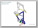
I am currently working on a new design for our drive train. The earlier mechanical designs had a lot of moving parts, like belts, chains & gears. The new electro - motive design has very few moving parts. It was inspired by the GE AC6000 CW & the GM-EMD SD90MAC diesel - electric locomotives. On this helicopter a person will be powering a D.C. generator, which is located between the pedals (fig. 1).
As per the competition rules, there will not be any energy storage device like a flywheel or a battery. The generator will convert the mechanical energy, provided by the rotation of the pedals to electrical energy. This energy will be fed to 2 D.C. brushless motors, located on the vertical shaft (fig. 2).

A D.C. motor was chosen because it can start under load which eliminates the need for a clutch. The brushless designs were the lightest motors available for the required torque & speed. Unlike conventional motors in which the housing remains stationary, here the shaft will remain fixed and the housing will be rotating. The outer blades will be secured to the upper motor housing by an octagonal hub (fig. 3).

The inner blades will be secured to the lower motor housing by a circular hub (fig. 4).

Depending of the polarity of the electrical input, the motors can me made to rotate in opposite directions. Unlike a mechanical gearbox in which the ratio of the speeds of the blades will be fixed, an electric drive train allows this ratio to be varied infinitely. Since it will be impossible to ensure that the momentum of the counter-rotating blades are balanced, I will also try to design a control circuit to automatically direct more power to the slower motor, if there is an unbalance, since the competition rules require one person on the craft to remain stationary.