
Math and the Internet is a summer course for advanced high school students. It is part of the Michigan Math and Science Scholars program, which is sponsored by several departments at the University of Michigan. The course lasts for two weeks, and we have class for 6 hours a day. It was originally developed by Jason Howald and Mark Conger, and in 2010 the instructors were Mark Conger (that's me), Sunny Fawcett, and Shashir Reddy.
We covered a number of topics, including error correcting codes, Google's Page Rank, several data compression algorithms (which led to discussions of fractals and Fourier series), and cryptography, which culminated when we learned the RSA public-key encryption algorithm and exchanged messages with another class doing the same thing. Pictures from all 10 days were posted for the parents and anyone else to look at.
We also spent 2½ days working on understanding computer hardware, from the bottom up. That means we started with transistors, Then we built logic gates, then we built NAND Latches to see how memory works, then we convinced ourselves that we could use our latches to build Flip-Flops. At each stage we took the attitude that if we'd built it, it was fair game to use a chip that someone else had built to do the same thing. So eventually we used 74LS00 (nand), 02 (nor), 04 (not), 08 (and), 32 (or), and 86 (xor) ICs for our logic gates, and 74LS74 ICs for flip-flops.
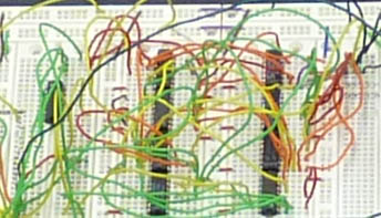
Pictures of our hardware exploits are available here and here . We used breadboards, power suppies, and workstations donated by Matt Smith of the UM Electrical Engineering and Computer Science Department. The reason EECS was willing to give them to us is that EECS students design all their circuits in an online simulator these days, and don't ever build with wires. Matt thinks this is a shame.
|
By the end of the first day we had built binary adding machines, with capacity up to 3 bits + 3 bits. That is, the user could key in a number from 0-7 in binary using a bank of three on/off switches, then do the same for another number on another bank of switches, and the sum of the two would appear as a binary number represented by 4 LEDs. The movie to the left shows an adder in process (not quite working yet), made by Sabrina Lato and Jonathon Racz. |
On the second day we learned how to make memory and then set an ambitious goal for ourselves: build a 24-hour digital chronometer by lunchtime of the next day. (We used the word "chronometer" because "clock" has a technical meaning—see below.)
The specifications were for 6 digits, H10 (the tens digit of the hour), H1 (the ones digit of the hour), M10, M1, S10, and S1, two each for hours, minutes, and seconds. We had purchased 6 large 7- segment LEDs from Jameco. Each digit required three parts to make it work:
S1, M1, and H1 need to hold values from 0 to 9, and pass from 9 to 0. S10 and M10 hold values from 0 to 5, and pass from 5 to 0. Finally, H10 holds values from 0 to 2, and passes from 2 to 0. There's also the added problem that H1 needs to pass from 3 to 0 if H10 is 2. That is, the next hour after 23 is 00.
We split the job into tasks, and everyone took on a task.
A flip-flop represents one bit of memory. That is, it contains a wire which is either at +5V or +0V. It's useful sometimes to call +5V "true" or "1", and to call +0V "false" or "0". This wire is memory in the sense that we can set it to a particular value, and then read that value later.
Well, that doesn't seem so impressive; after all, you can set a wire to a given voltage just by attaching it to either +5V or +0V. What makes the flip-flop so useful, though, is that there's a time delay between reading it and writing it. Here's how it works:
So Q is like "the president" and D is "the president elect". When the clock ticks, the president elect is promoted. This timing mechanism turns out to be the key to making a computer, because it allows things to happen is a proscribed order, rather than all at once. In other words, you can write computer programs which do one thing, then stop and think before deciding what to do next.
Our registers need to count from 0 to some maximum value, and then roll back to 0 again. But most don't increment each second. S1 does, but S10 increments every 10 seconds, M1 evey minute, M10 every 10 minutes, H1 every hour, and H10 every 10 hours. So each register needs to be told when it's time to increment. Therefore it needs an input wire, which we'll called INC, which is 1 if the register should increment the next time the clock ticks, and 0 if it should not. INC(S1) can be wired to a switch, and then we can start and stop the clock with the switch.
But what about the other INC's? How do we decide when to tell, say, S10 to increment? Well, it should only increment when S1 is changing from 9 to 0. That is, when S1 is "overflowing": being asked to increment when it's already at its maximum value. Likewise, M1 should increment when S10 is overflowing, M10 when M1 is overflowing, etc. So each digit should have an output, OVR, which will be attached to the INC of the next digit.
We need one flip-flop for each bit our register will have. Let's say we're making S1. It needs to hold values from 0 to 9, so it requires 4 bits, which is to say, 4 flip-flops. Call the bits Q0, Q1, Q2, and Q3 in order from least significant to most significant. We use Q to remind us of how the flip-flop works. Then incrementing is like adding INC to the number Q3Q2Q1Q0. That is, doing the addition problem
| C3 | C2 | C1 | ||
| INC | ||||
| + | Q3 | Q2 | Q1 | Q0 |
| R3 | R2 | R1 | R0 |
where the C's are the carry bits (just like the way we all learned to do addition in 2nd or 3rd grade). So R0 is the sum (mod 2) of INC and Q0, which is to say, R0 = INC xor Q0. Likewise, R1 = C1 xor Q1, and so on. We'll need to carry to the 2's column only if the sum in the ones column is at least 2, which only happens if INC and Q0 are both 1. So C1 = INC and Q0. Similarly C2 = C1 and Q1, and so on. In fact, if we accept C0 as an alternate name for INC, we can summarize the rules as
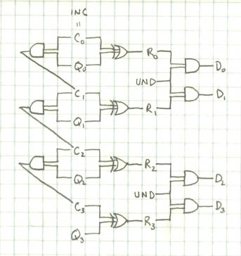
So what should we do with the R's? Well, they should be the next values of the register, so we should send them to the D pins on the flip-flops, of course. Well, almost. We want to do that unless the register is about to overflow, in which case the D's should be set to 0. So here on the left is a proposed scheme for the counting part of the register. UND = not OVR.
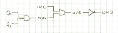
The rest of the register needs to compute OVR and UND, the former for output to the next digit, and the latter for use by the counting part. This part will be different for each digit, since their max values are different. For S1, the max is 9, so this scheme will do:
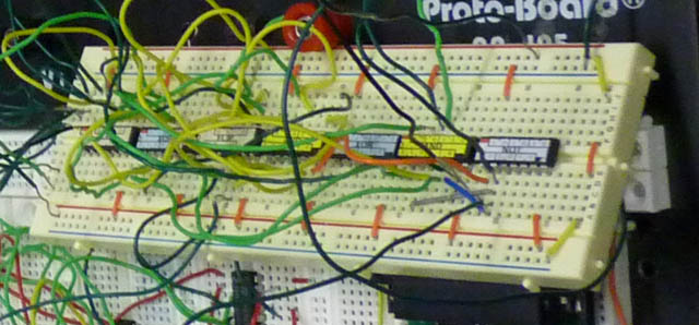
The final challenge is, of course, to build that using ICs. Here is one built by Jeff Walker, Nicholas Zajciw, Effie Landau, and Aaron Fein. (They didn't have the benefit of the labels on the chips; I only thought to stick those on later.) If you look closely you can see that three of the flip-flops are being used, so this is a 0-5 register.
The second part of a digit is the logic which takes the register bits (which describe the value of the digit in binary) as input and for output produce a 0 or a 1 for each of the 7 segments of the LEDs. For technical reasons, in this case, 0 means "on" and 1 means "off".
For example, consider the top right segment. It should be on for most digits—in fact, for all of the digits 0-9 except 5 and 6. So here's a truth table connecting register bits to that segment:
 |
|
|
Now the challenge is to find a series of logic gates which can be applied to the Q's to produce the right column, and thus control the top-right LED segment. Our 6 students from Gyeonggi Science High School in South Korea, Jihoon Choi, Seung Hyeon Jo, Yong-Jik Kim, Bryan Dong-ik Lee, Su Young Lee, and Ju Sang Lee, worked on this problem, for both the 0-5 LEDs and the 0-9 LEDs. Note the Korean 7 in the list above—it has an extra vertical bar in the upper left. (Double-click the movie on the left to see a test.) They came up with logic for each segment in each case. For the top-right segment of a 0-9 LED, they came up with this operation: |
|
The reader can check that that will be 1 for 5 and 6, and 0 for all the other digits. That was one of the simpler segments—some required as many as 5 gates. They figured out logic for all and then built it as efficiently as possible, because space on the boards was tight. The picture on the right shows how the LED logic looked for a 0-9 segment. |
|
Each LED segment contains 5 LEDs, and the voltage drop across each is about 1.6 volts. They're wired in series, so the total drop is about 8 volts, which is too much for our 5-volt logic circuits to power directly. The recommended current is 30 mA.
We borrowed a 14-volt power supply from writer, electrical engineer, ham radio operator, and friend of the class Dan Romanchik. Dan and I struggled for most of an evening to find a good way to control the LEDs, and finally settled on using a relay for each segment. So the basic setup is this:
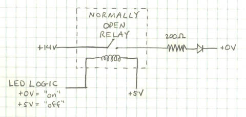
We actually ended up using 220 ohm resistors instead of 200, which makes the current
which is close enough to the target of 30. The task of setting up the relays required care but not ingenuity, so in the interest of time, Sunny, Shashir and I did the wiring. A typical setup for 7 segments plus the decimal point looked like this:
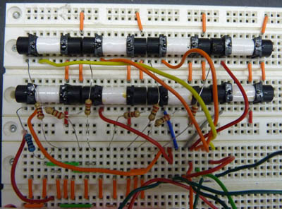
The one blue resistor in the picture is 1000Ω, and it's for the decimal point, which only has 1 LED. The pins of the LEDs are off the bottom of the picture, and the cluster of wires in the SE corner shows where the logic wires plug in.
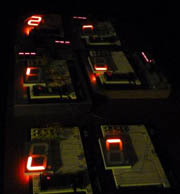
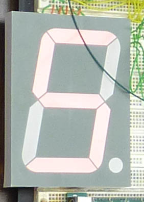
We worked on the digits all day Thursday 7/15. That evening Shashir and Sunny and I installed the relays, and tested to make sure we had enough power to run all the LEDs at once. The logic for one of them, H10, which goes from 0 to 2, was completely working. It was built by Michael Lacy and Brian Chantrupon, and it's the "2" in the upper left corner of the picture.
The next morning we marshalled on. I had announced to all the other instructors, and to the students, that we would have a show at noon to display our accomplishments. So the pressure was on.


