


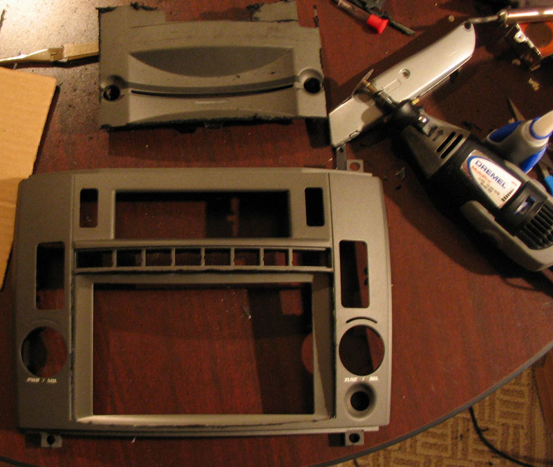
After I removed and gutted the radio, I took the face plate and cut out a rectangular hole using a Dremel tool. I disassembled the Lilliput LCD casing and placed the bezel behind the hole to make sure it fit. The picture shows that the bezel fit almost perfectly.
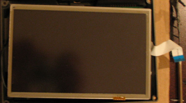
Here's a photo of the LCD panel removed from its bezel:
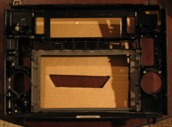
I superglued the bezel from the back of the face plate to secure it.
This allows me to use the LCD's original mounting brackets and screws to secure it
to the face plate.
Bondo was applied around the front edge of the bezel. After
days of filling and sanding, the two pieces were molded together so they
looked like one piece.
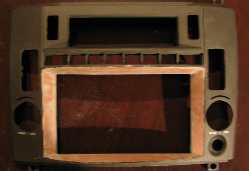
A few coats of spray paint makes it so you can barely tell that the
piece was modified.
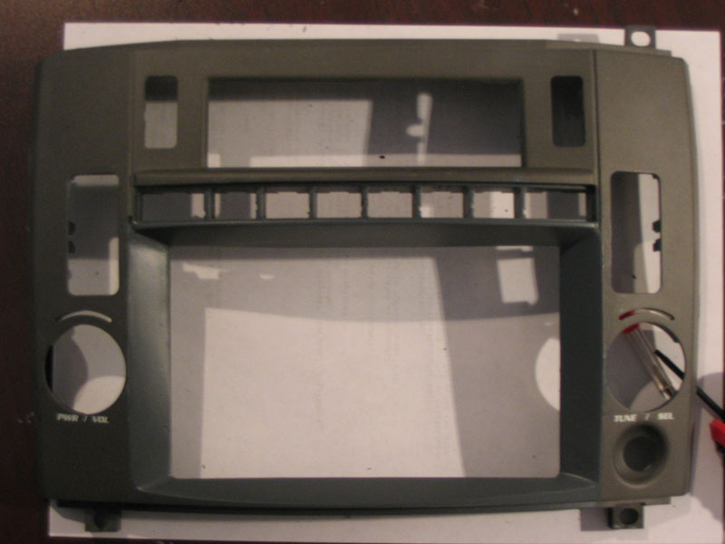
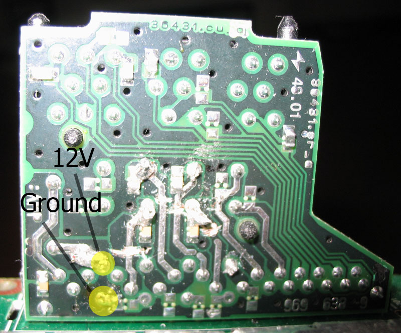
I had to cut the circuit board and plastic bracket that was in the faceplate in order to make room for the new screen and the LCD controller. I also modified the LCD controller board by soldering the 12V and ground leads of a Molex power connector to the power input of the LCD controller. This allows the LCD to be powered off the ATX power supply instead of a barrel plug and cigarette adaptor. Putting the dash back together with the new screen required several small tweaks that I won't get into. Instead, I'm going to move on to assembling the computer behind the screen.
Power and Sound Integration
Having a computer in the CTS is useless if it doesn't have power or
can't pump audio through the car's amplifier and speakers. To
conquer the power issue, I used the M1-ATX power suppy (see the
hardware section). The power supply is
specially made to handle a variance of input voltages from 5V to 16V.
The regulated power is output through a standard ATX power harness.
It also has a 12V sensing circuit that turns on or
hibernates/suspends/turns off the computer with the car's ignition.
The sensing wire must be spliced into a switched 12V power source that
becomes hot with ignition. I found a 12V switched power source in
the climate control panel harness underneath the radio. Constant
12V power was provided by the power harness of the factory radio.
This was done by soldering the the power wires of the power supply onto
the power pins in the harness plug riser card on the radio circuit board
shown below.
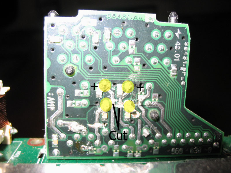
The audio integration was accomplished
by cutting the RCA plugs off one
of the RCA to mini-plug adaptors and soldering them to the appropriate
output pins on the harness riser board of the factory radio circuit
board. Certain traces were cut on the board in order to disable
sound output from the factory radio. The cuts need to be made deep
into the board to insure zero conductivity. This must be done in
order to prevent amplifier overload or shorting. This will not
disable OnStar, chimes, or the steering wheel controls.
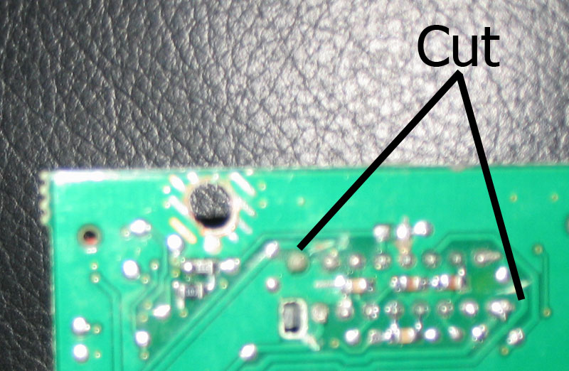
Two additional traces need to be cut. These are located on the
underside of the board beneath the rear MOSFET chip.
Computer Assembly
The Mini-ITX motherboard was small enough to make everything in the
computer fit behind the dash. All the boards were orientated
vertically. In the order of closest to dashboard to the back of
the radio, the boards were placed in the following order: factory radio
circuit board, power supply, motherboard, firewire/USB daughter board, hard drive. The hard
disk was fastened to the rear radio casing vertically by drilling holes
into the case and using the supplied mounting screws. The harness
plugs were relocated to the bottom of the radio instead of the rear.
The I/O panel of the motherboard is also exposed to the bottom of the
radio. To reduce heat build-up, the bottom and top metal panels of
the radio casing were removed. No pictures are available at the
moment but I will get them up soon.
Installing Into The CTS
Now that everything is bundled up inside the radio casing, it's time to install it all back into the CTS. I had to use a Dremel and shave off some of the plastic below where the radio sits in order to expose all the ports of the I/O panel on the motherboard. After the trimming, everything fit snuggly behind the dash. The 12V sensing wire needs to be spliced into the appropriate wire on the climate control panel harness. I can't remember which one it is but it can be easily found using a multimeter. Next, plug the factory harnesses into the radio circuit board. These harnesses will provide power and accept sound from the computer.
Plug the LCD panel into the VGA out on the motherboard.
All the USB devices should also be plugged into the motherboard.
I routed the GPS receiver underneath the steering column and up into the dash below the windshield. This moves it away from interference and gives it a clear view of the sky.
The XMDirect unit plugs into the serial port of the motherboard. There is also an RCA to mini-plug cable that needs to be connected so that sound can be sent from the XMDirect unit to the audio line-in of the computer. The module was fastened underneath the steering column and the antenna was mounted on the roof of the car.
The DVD drive was secured in the glove compartment on the top shelf and was connected to the computer using the USB 2.0 enclosure. I cut a small hole into the back of the top rack of the glove compartment so that a USB cable could be passed through. I attached the DVD drive to this cable which also provides power to the drive.
I also got a USB extension cable and exposed it underneath the ashtray so that I can attach USB peripherals, such as keyboards and flash memory, if I need to.
Now it's time to set up the software.