 |
|
Angler's Underwater Horizontal Panning Video Unit |
Navigation: Underwater Data Gathering
by
Larry "Harris" Taylor, Ph.D.
This
material is copyrighted and all rights retained by the author. This article is
made available as a service to the diving community by the author and may be
distributed for any non-commercial or Not-For-Profit use.
All
rights reserved.
Go To: Home About "Harris" Articles Slides War Stories Editorials Links Fini
Jump To:
Video Camera Deployment Line Chest Harness Shore Baseline Underwater Baseline Markers Crate
Tie-Wrap Holder Measuring Stuff Plumb Bob Grids Data Board Entering Data Drawing Stuff Graph Paper
Although underwater sight-seeing is a delightful activity, many recreational divers are searching for more meaningful underwater activities. One such activity involves working with underwater scientists to gather data to better describe our underwater environment or maritime heritage. Much of the equipment used for gathering these data is, either because of budgetary or non-existence status, home-made. This article describes some of our data collection tools with an emphasis on underwater mapping/surveying.
In general, sites to be explored are defined by historical records, folklore, previous underwater searches with sonar or video observations, or just plain curiosity. This article summarizes some tools that we have used for exploring existing sites, as opposed to searching for sites to explore.
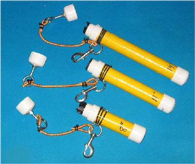
More than two decades ago, a noted underwater archeologist told me that the cardinal rule for all divers on underwater exploration missions was to return to the boat with the same number of (or more!) tools they had in their possession when they descended to the work site. In keeping with this "prime directive," all our gear has wrist lanyards and/or clips (we prefer the X-Large stainless steel variety to facilitate operation when wearing dry gloves) to hopefully ensure possession of underwater tools. We tend to rely on eye-splices and carabineers whenever possible since this combination is extremely durable and reliable. We use polypropylene (typically black in color) tie wraps to attach clips to tools ... 2 or 3 tie wraps per connection.
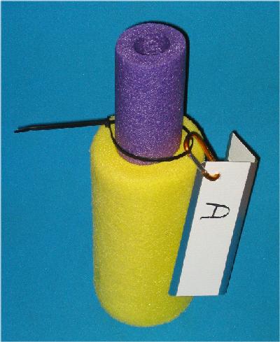
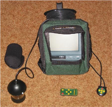
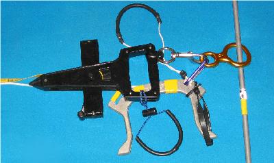
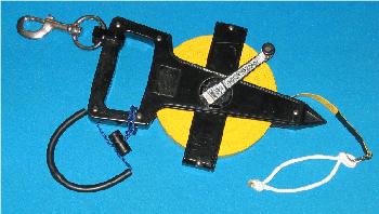
It is often convenient to have an idea of a potential dive site before entering the water. Since commercial-grade video monitoring systems and ROV's are quite expensive, we sometimes use a relatively low cost (~$300.00) alternative that can be useful in the recreational, public safety, or scientific diving communities. This is a fisherman's video camera. Although intended primarily to look for a fish population, it can be useful in shallow diving operations. Ours is a Cabela's Advanced Angler II panning underwater camera. This is a weighted, submersible B&W video camera with 360 degree panning capability, 65 feet of video cable (the cable reel serves as a carrying handle), wireless control of scanning, self-contained red LED lighting, a battery (with charger) that typically lasts 6-7 hours of continuous viewing, and a 7" B&W monitor. The carrying case has built-in light shades for the monitor. The 13.5 pound unit is shown below.
|
|
Angler's Underwater Horizontal Panning Video Unit |
Video Camera: "Downward Looking"
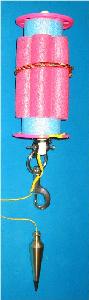
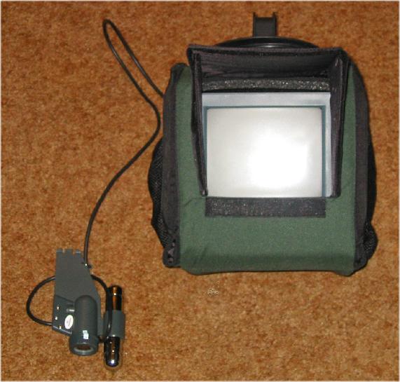
Another, less expensive system (Cabela's Advanced Angler, ~ $200.00) is a Sony video camera mounted on a downrigger weight. This is a fixed view camera without panning capability. However, a tie-wrap around the camera cable attached to the downrigger fin alters its viewing angle by about 90 degrees. This converts the camera into a strictly down-looking camera. This system is essentially the same as the above Advanced Angle II system, except the camera unit does not alter direction of view. The camera contains an adjustable brightness self-contained lighting system. The 14 pound unit is shown below.
 |
|
Angler's "Downward-Looking" Video Unit |
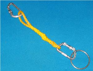
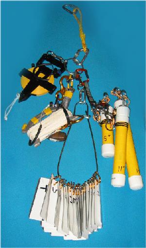
It is often cumbersome for divers to carry tools, especially in rough water, when dangling or hand-held tools can complicate entry/exit from the dive boat. So, we typically drop the tools into the water using a separate line. The divers descend to the work site, move to the deployment line, grab the appropriate tools, use the tools for the dive, and return the tools to the deployment line prior to ascent. This also facilitates sharing of not-used-for-whole-dive tools among different dive teams. We use a short double eye-spliced line (below, left) with locking carabineers and a 4" stainless steel ring (for attaching gear with clips) as our "deployment device." At the work site, this short line is attached to a line of the appropriate length for the depth of the work site. With more cumbersome or abundant items, a short mini-shockle line or climber's double carabineer can be used to hold items.
 |
 |
|
Tool Deployment Line |
Tool Line with Tools |
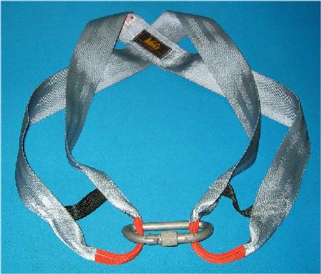
It is frequently necessary to carry "mission-specific" tools from the deployment line to the to the work site. We use a climbing harness secured with a locking carabineer at the center of the chest (worn under the b.c.d.) for these tools. (Ours were obtained from REI decades ago ... we like this particular model since the harness, except for the added locking carabineer, has no metal parts to corrode.) With this scheme, "diving stuff" is carried on the D-rings or pockets associated with the backpack or buoyancy compensator and "work stuff" tools are carried on the chest harness. This puts the tools right in the center of the chest where they can be easily manipulated during the dive.
 |
|
Chest Harness |
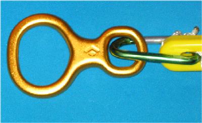
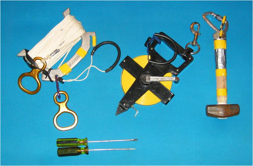
Baselines are the reference line from which trilateration measurements are made. On shore (see Near Shore Mapping), we use a 100' diver's line (same line as we would use underwater ... the line holder with a wrist lanyard has yellow duct tape markings for added underwater visibility) as the baseline. The addition of gold climber's figure eights (below, left) to the handle and the end point of the line provides a convenient means of pulling the line taught and then rapidly securing the line to the ground with a screw driver (Screw drivers are easy to find, embed, and to remove when the project is over.) driven through the opening of the figure eight with a small sledge hammer. This type of hammer is small (for convenient storage and carrying underwater), has a large striking surface, and its mass provides a more-effective-than-conventional-carpenter's-hammer underwater driving force. In addition, the wooden handle can be easily drilled to provide a means of attaching clips to the handle. We added some yellow duct tape to the handle for increased underwater visibility and a carabineer to hook it to either the deployment line, our underwater baseline poles, or a diver. After the baseline is in place, we add a surveyor's line (ours have a wrist lanyard and clip added for underwater use ... there is no need for these attachment points if the surveyor's tape is only used on the surface) along the nylon line for distance measurements. The nylon line adds strength and security to the surveyors tape. The tools used for our on-shore baseline are shown, below, right.
On shore, surveyor's tapes of 200' and 300' can also be used.
 |
 |
|
A Figure Eight |
Equipment Used For An On-Shore 100' Baseline |
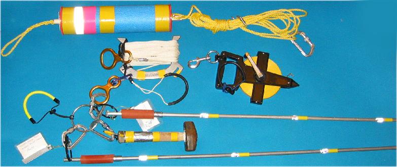
Our underwater baselines use the same nylon lines on a handle with figure eights as the on-shore baselines, but the underwater environment makes deployment a bit more tedious. Instead of screw drivers with a 6" blade to secure the baseline, we use 1/2" aluminum rods ... ours are 4', 6' or 8' in length. For added underwater visibility of the aluminum rods, we added yellow tape marks and 3M reflecting tape at one foot intervals. A short piece of vacuum (thick rubber) tubing provides a hand-hold to assist driving (using the small sledge hammer) the poles into the bottom. Each aluminum rod has a large carabineer (attached via 3 tie wraps threaded through a small hole drilled near the top of the rod) to facilitate carrying everything needed for the baseline to the work site. These are the same poles we use as ranges in a near shore mapping exercise. Basically, the first aluminum rod is placed through the figure eight at the end of the 100' line and driven into the ground with the sledge hammer. A swim noodle float is attached to the carabineer on this first pole. The float marker makes finding the line much easier during long-term projects and also gives a location marker for the surface support crew for accurate surface position determination of the line end-point. (The results of this operation are shown below, lower left image). The hammer and the second pole are then carried by one diver (who navigates if the line is to follow a specific compass heading) as the second diver unwinds the baseline. When the line is completely deployed, the line is drawn taught and the second pole is driven through the figure eight on the line handle. The hammer can be left on the carabineer on the aluminum rod or returned to deployment line. A second float can be attached, if needed, to the carabineer on this end-point pole. This end of the line is shown below, lower right image.
To facilitate initially carrying all this stuff to the starting point, everything can be clipped to a large (4") stainless steel ring, carried to the dive site, and unclipped as needed.
Lastly, for long-term projects, each pole contains a laminated business card with a "Please do not remove" request on the back side of the card.
 |
|
Equipment Used For An Underwater 100' Baseline |
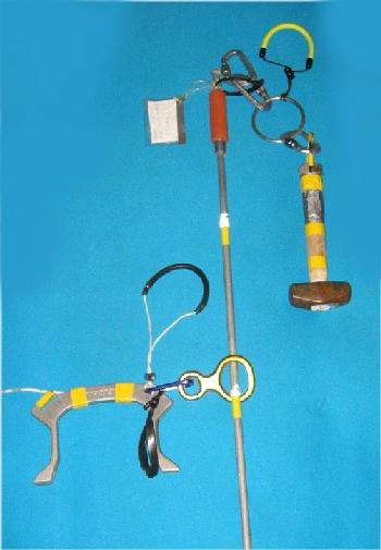
To clarify this system, below is a representation of the deployed set-up. In reality, the figure eights would be on the bottom. For purposes of illustration, the figure eights are shown below near the top of the aluminum rod.. When the divers leave the first rod (below left), the swim noodle marker would have been deployed to mark the site to surface personnel. The terminal end of the line is shown is shown below, right. If needed, an additional swim noodle marker can be added to the attached carabineer. This particular handle can be pushed into the ground to provide a bit more stability to the baseline.
 |
 |
| Initial End Of The Baseline | Terminal End Of The Baseline |
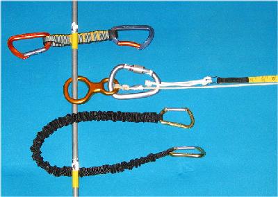
The baseline shown above is used primarily for search and recovery operations or for determining kick-cycles. Although the line is marked every 5 feet, addition of a surveyor's tape allows the baseline to better serve as a point of measurement for underwater trilateration of sites along a primarily flat surface. The tape holder end of the surveyor's tape is secured to the terminal end figure eight of the baseline with a large stainless steel diver's clip (below right). The zero point of the tape is secured (using the 1/8 camper's line loop) to the baseline figure eight with a large carabineer (shown, below left) ... the surveyor's tape can also be secured with a a climber's double carabineer (shown above the attachment in the left image) or a mini-shockle (shown below the attachment in the left image). Finally, the surveyor's tape can be attached to the baseline at appropriate intervals with tie-wraps. This arrangement is shown below.
 |
 |
| Initial End of the Baseline | Terminal End of the Baseline |
When the object to be mapped varies significantly in distance above or below the baseline, then the anchoring aluminum rods are placed outside the area to be mapped and the surveyor's tape is attached to the nylon line at convenient points on the object to be mapped. In this manner, the line can be held taught with minor impact on the site being measured. If the distance above the bottom is significant, then a line much longer than 100' will have to be used as the securing line for the full length of a 100' surveyor's tape to be used in underwater measuring operations.
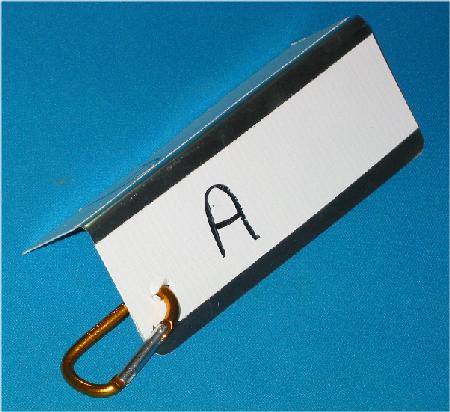
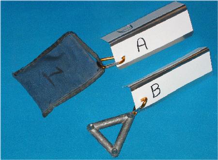
It is necessary to mark and describe objects that will be placed on an underwater grid plot. These markers can be anything from plastic strips cut from consumer products to formal forensic evidence markers. Ours are made from aluminum Step Flashing obtained from the roofing section of a home improvement store. These are 5" x 7" (12.7 cm x 17.8 cm) thin aluminum strips that are commonly sold in 10-packs for a couple of dollars. After a 15/32" hole for a non-climbing carabineer is drilled near a corner (the entire package of 10 is clamped together and drilled all at once to ensure that the holes are coincident), the strips are folded lengthwise to form an inverted V-shape. We use a strip of white duct tape on both sides as a writing surface and label each marker with permanent black ink. Lastly, we file down the corners to minimize sharp edges. We only use alphabetic characters for markers to minimize confusion with numerical measurements on the data sheet. A completed marker is shown below, left. In areas where there is concern about markers being moved, a weight (typically, a diver's weight belt pouch, a standard weight-belt weight (using a tie wrap), or a fisherman's 2 pound triangular weight) can be secured with the small carabineer as shown below, center. For some objects, a polypropylene tie-wrap can be used to secure the marker to the object (below, right).
 |
 |
|
| Data Location Marker | Markers With Weight | A Marker Secured With Tie Wrap |
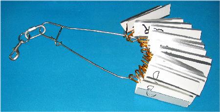
The carabineers also allow the markers to be easily carried (using a fish stringer, with added clip) for deployment, During preliminary survey of the site to be investigated, one diver removes the markers, one at a time, from the stringer, attaches a weight, if needed, and places a single marker on or near the object to be mapped/observed, while a second diver records the marker designation and a description of the object being marked. A stringer with 20 markers is shown below, left.
 |
 |
|
Markers On A Stringer |
4-Pound Weight Belt Weight As A Marker |
Another marker system uses diver's weights, above, right. The weight is wrapped in white duct tape and marked with waterproof ink. A large (22" for width/strength cut down to a few inches) tie wrap provides a means for carrying these weights on a stringer or by hand.
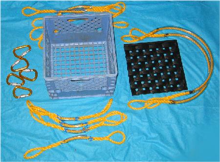
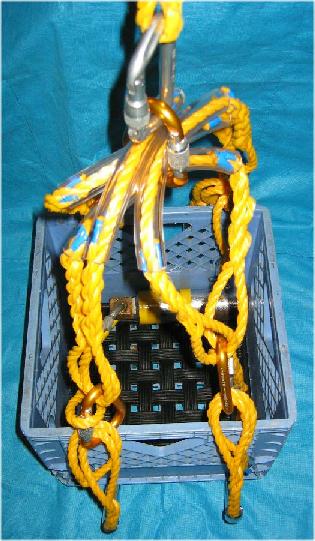
For transporting weights between the surface and the bottom, we use an old-fashioned milk crate with a padded (outdoor rubber mat trimmed to size) bottom and a few lines (with clear Tygon tubing acting as an abrasion guard) and carabineers for attaching top a either a lift bag or ascent line. This system easily handles 60-70 pounds of weight.
 |
 |
Milk Crate Components | Assembled Milk Crate |
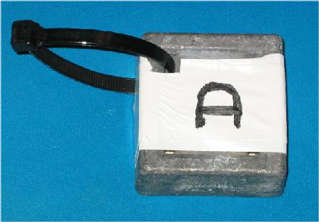
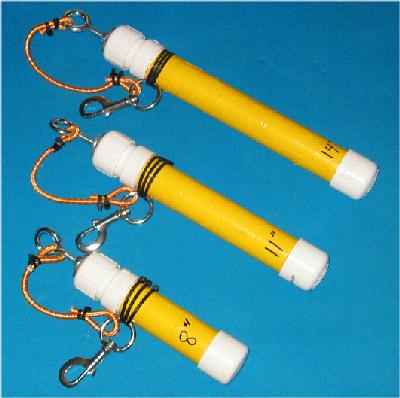
Tie warps (cable ties) are a convenient means for securing any number of objects. We have standardized on 8", 11" and 14" lengths. (Polypropylene tie wraps, commonly black in color, are preferred since polypropylene is extremely hydrophobic and resists absorbing water; nylon tie wraps, commonly, but not always, white in color, absorb water and, over time, become quite brittle and break.) The small size of tie wraps can complicate using them at depth, especially when the diver is wearing gloves. We carry tie wraps underwater in a 1 1/2" PVC tube with added bottom cap, screw top and a large stainless steel diver's clip. A small fishing weight held in place with aquarium cement in the bottom cap facilitates an upright position for the carrying case. (We use a significant amount of cement so that, after drying, the bottom cap will have a uniform smooth surface. To minimize loss of the screw-threaded top, a swivel in the top piece is connected to the dive clip with a small piece of bungee cord. (Caution: Over-tightening any PVC threaded connection makes it extremely difficult to open underwater.) Finally, a yellow duct tape wrap increases in-water visibility. Our containers (which each hold ~70 tie wraps) are shown below.
 |
 |
| PVC Pipe Tie Wrap Holders (Closed) | PVC Pipe Tie Wrap Holders (Open) |
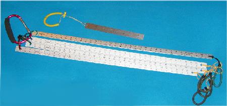
Creating an map/chart/image of an underwater site involves an enormous amount of time taking and recording measurements. Anything that has a waterproof, readable scale can be used. The most common measuring tools are fiberglass tape measures (from quilt or fabric shops), stainless steel rulers, and fiberglass surveying tapes.
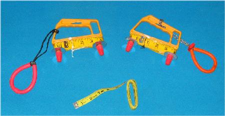
Fabric rulers typically are found in 60" and 120" lengths. The 60" rule is typically used as is, but the longer 120" rule may become cumbersome at depth. So, our 120" rules are wound on a spool (construction of these is found in Measuring Distances). Metal rulers are typically one foot or three foot stainless steel. We added small carabineers to allow them to be attached to a deployment line and wrist lanyards to facilitate maintaining possession of the ruler during the dive. A large non-climbing carabineer makes a convenient means of storage as well as for dropping the rulers into the water via our deployment line.
 |
 |
| Fabric Rules | Metal Rules |
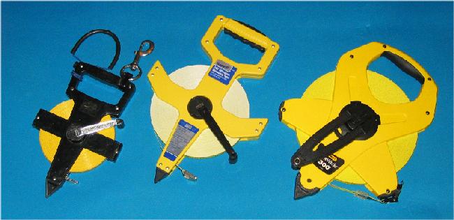
Fiberglass surveying tapes typically are found in 100', 200' and 300' lengths. The 100' length is the most commonly used underwater surveying tape. Tapes larger than 100' can be awkward/cumbersome to use underwater. We added a stainless steel x-large diver's clip clip (for attachment to the deployment line or the baseline) and a wrist lanyard (for the diver) to our 100' surveying tapes to facilitate maintaining possession of these tools while underwater. These surveying tapes typically have an English (Imperial) scale on one side and a metric scale on the other side. When deployed underwater, we add a small loop of 1/8" camper's line to the zero-point end of the tape to facilitate holding the tape in place. This is shown, below right.
 |
 |
|
100,' 200,' and 300' Fiberglass Surveying Tapes |
Surveyor's Tape with Zero Place Holder |
Plumb (from the Latin, plumbus, meaning lead) Bobs are weighted lines used to establish a straight vertical line. In underwater surveying, plumb bobs are used to simplify taking measurements in a three dimensional environment. Trilateration (using 2 distances from a baseline) is a planar measurement (assumes all measurements are made on a flat surface). As such, it does not account for differences in distance associated with objects not on the flat surface of the baseline.
For example, assume you are measuring an object at point A in the diagram below. If the baseline is laid at point B, then your direct in-water measurement from the object to the baseline is the green line distance AB. If you were to plot this AB distance on a chart (represented by the magenta line, DE) post-dive, your distance (green line at the bottom of the image) on the chart be too long (you would indicate that object A is farther from the baseline that it actually is). This is because the linear measurement AB does not include any angular (distance above or below the plane of the baseline) information.
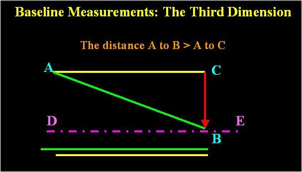
One way of placing the object at A on a flat chart at the correct distance from the baseline is to use a plumb bob. The plumb bob defines the vertical red line CB in the diagram above. So, the diver would measure from point A to the deployed plum bob line at point C. This in-water distance is the yellow line, AC. Then, post dive, the distance AC would would be plotted on the chart.
A comparison of the two lines is represented by the green and yellow parallel lines at the bottom of the image.
In other words, if we want our plotted chart to correctly represent an "aerial image" of the mapped area (photo taken high above the entire area), then we would have to plot the object A at the yellow line distance AC, and not the direct distance, green line AB.
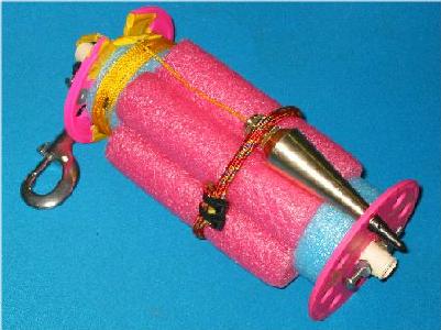
In-water plumb bobs are simply a weighted line and a float to establish a vertical line. These can be as simple as any weight and a piece of foam. Since we had have a lot of swim noodle based floats, we applied the same technology to our plumb bob. It is certainly more elaborate than need be. However, its size facilitates in-water handling with dry gloves and having a clip on the device makes it easy to carry and deply. The 10 foot line is easily recovered after deployment by simply using the end handles ... holding the device in a horizontal position and turning the device raises the line until the bob is acquired and secured with the bungee cord. Our plumb bob is shown below, left, and as it would appear when deployed, right
 |
|
| Swim Noodle Based Plumb Bob | Plumb Bob in Deployed Position |
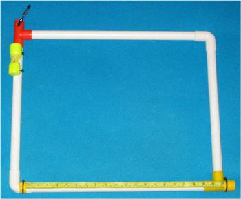
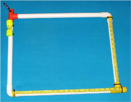
Grids are a rectangular or square framework used to establish coordinates for measurements. They range from simple PVC pipe frames to elaborate metal matrices. For recreational divers, they are commonly small PVC frames used to document (either by photographic or trilateration measurement) small objects. Our small grids were made from a discarded child's toy called Ladder Ball. This toy provided a source of already prepared small (1") diameter PVC lengths and connectors. A simple grid for measuring objects is shown on the left. For photos, a second scale helps establish correlation between object on the bottom and the resultant image.
 |
 |
|
Measuring Grid |
Photo Grid |
Typical PVC grids use all elbow (right angle connectors ... like the connectors in the lower left and upper right of the PVC grids above). This creates a trapped air space within the framework that results in a buoyant frame. By using two T-connectors (at the upper left and lower right of the grid frames above), the trapped air space (and resultant buoyant force) is avoided as the frame fills with water through the open T-connectors. (The large opening also provides an opening for post-dive flushing the interior of the grid framework with clean water.) The T-frame is a convenient place to place a small non-climbing carabineer for attaching a clip or cord to facilitate storage or transport.. On the upper left of the grid above, a small (60") fiberglass tape measure is held between 2 scuba tank valve protectors. This tape can be for trilateration measurements of objects within the frame. The baseline for these measurements is a fiberglass measuring (both Imperial and metric scales) tape held to the plastic pipe with a yellow duct tape wrap. The duct tape wrap is secured with a black polypropylene tie-wrap.
Sometimes it is necessary to place the location of the small grid within the context of a larger site. This is usually accomplished by trilateration measurements of the small grid frame with respect to the primary site baseline. These measurements are made from the corners of the grid frame ... using different colors on opposite corner minimizes confusion on which corner was farthest away from the primary baseline.
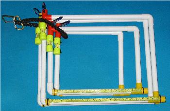
Several frames can be stored or transported together (below left) using a bungee cord alternative, the mini-Shockle (below, right).
 |
 |
| 4 PVC Grid Frameworks Secured For Transport | A Mini-Shockle |
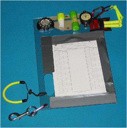
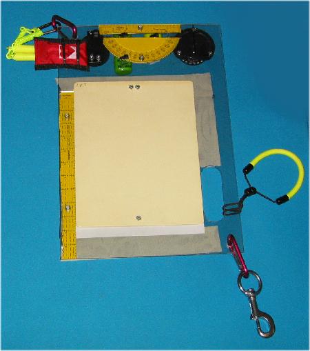
There are far too many measurements made on an underwater survey site to rely on memory. So, much of the tedium associated with underwater surveying is the seemingly never ending cycle of measure something and then record the measurement. In many cases, a large (8.5" x 11" or larger) diver's slate is sufficient. Some divers will use an acrylic or aluminum clip board to hold Mylar sheets for recording data. Unfortunately, these typically contain metal springs to furnish clip tension and over time, the metal spring will corrode and fail. So, many folks will not use "clipboards" ... instead they will secure their underwater data sheets to the data board with liberal amounts of duct tape.
As the complexity or number of the measurements increases, it is convenient to customize your own mission-specific data board. These are usually home-made. They can be made of any waterproof material. Plexiglass (acrylic) and Lexan (polycarbonate) are the most common materials. Ours were made from 2 thin 12" x 14" sheets of Lexan (its what we found at a local home improvement vendor) bolted together to provide more strength. In general, polycarbonate (used to make jet canopies) is less brittle and much stronger than arcylic.
The hand-hold was cut out using a Dremel tool. Our surveying data board is shown below:
 |
 |
| Data Board - Front | Data Board - Back |
The components of the our data board ... Front, moving left to right, from top to bottom
Compass: Used for establishing bearings of baseline or other points.
Mr. Clean Magic Eraser (stored in a empty cylinder valve protector): Provides a convenient way to erase pencil marks on underwater slates or synthetic underwater data sheets.
Fabric tape: This is a 60" measuring tape secured between two cylinder valve protectors held to the board via tie wraps.
Analog bottom timer: These (Princeton-Tectonics) are no longer being made (ours are over 25 years old). These are easily read, totally reliable, durable timing devices that display total time (without the annoying reset common in many digital devices). Since they are spring-wound, there is no battery to die or replace. Having a bottom timer on the data board keeps this information readily available for the diver ... the diver can focus on data collection without having to stop data collection to check watch, computer, or instrument console for bottom time.
Trident SL-13 pencil: This is a large stick of graphite surrounded by a hard plastic case. The pencil has a tension coil to attach to the data board (or any size slate or console). On the data board, we use an empty emergency CPR face shield (from American Heart) container as a pocket to protect the graphite tip. We carry 2 pencils in case one is lost, broken, or uses all of its graphite during a dive. The pencil cord is secured to the board via a couple of non-climbing carabineers.
 |
 |
| Trident SL-13 | An Open SL-13 (showing graphite rod) |
Data Sheets: These are single sheets of plastic underwater paper ( Xerox 3R3118 Never Tear or RiteInTheRain 6511) that can be pre-printed (using a laser (not ink-jet) printer or xerography based copier, with data collection forms or templates. (RiteInTheRain does have waterproof paper that can be used with an ink-jet printer. However, this paper will not accept writing done in pencil ... must use a special waterproof ink pen.) These sheets are held to the data board with ample amounts of duct tape.
Wrist Lanyard: A convenient way for the diver to maintain possession of the board while collecting data ... the left wrist goes through the lanyard and the left hand holds the board by inserting the hand into the hand hold ... this holds the board in place and stabilizes the writing effort. Left handed individuals can temporarily use the same board with the back-side as the primary writing point or permanently reverse the front and back sides of this configuration.
Diver's Clip: A large stainless steel clip is attached to the board with a non-climbing carabineer. This allows attachment of the board to the chest harness or deployment line.
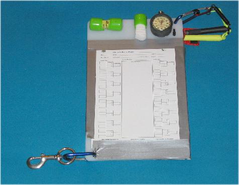
The components of the our data board ... Back, moving left to right, from top to bottom
CPR face shield case (from American Heart): Keeping pencils in a case is more convenient than simply letting them dangle.
Protractor: A strip of yellow duct tape on the board facilitates reading the numbers.
Quilter's Rule: This a a 12" ruler. A piece of yellow duct on the board makes the numbers easier to read.
Diver's Slate: This is an 8 1/2" x 11" traditional diver's slate. This is used for additional data, sketches, or diver-to-diver communication. The slate also adds some rigidity to the board. If needed, another sheet of underwater paper can be secured here with additional duct tape.
A Less Elaborate Board
A much less elaborate (and far less expensive) data board can be made from an inexpensive plastic cutting board that can be found in the kitchen supply area of discount stores. The board can be quickly assembled by drilling a few holes and attaching bottom timer, eraser, fiberglass tape holders, and pencil holders with tie-wraps. This board is most useful for missions where sketching is more important than detailed measurements or as a less expensive device for students taking underwater surveying courses. Our "cutting board" is shown below. Pencils will not write on the surface of the board, so data is collected on waterproof paper secured to the board with duct tape.
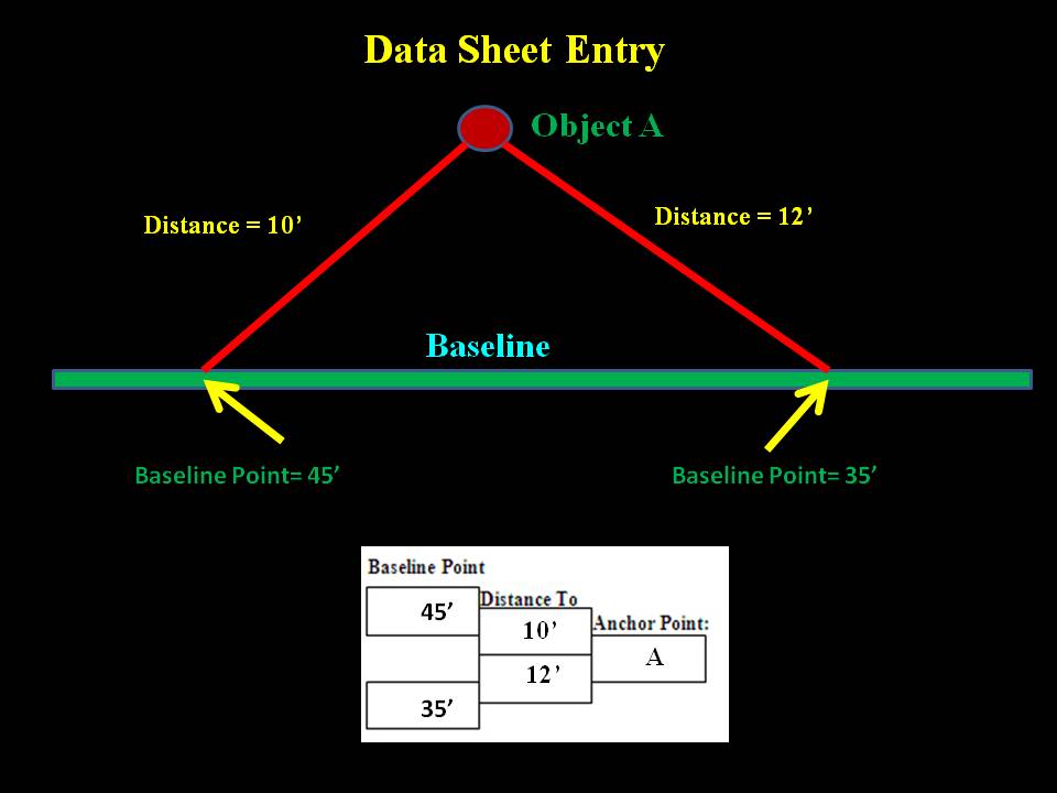
In practice, distance measurements are made as a 2-person team: One person serves as an anchor and maintains the zero position of the measuring tape on a designated, marked and described point. The second person (with both the data board and the surveying tape) moves away from the anchor to the baseline to measure and record the mission-designated points to be measured. The format of the data sheet (PDF versions of our data sheets (Based on the MAST data form) in two formats are available for download: with the umich Logo.pdf and without umich logo, No Logo.pdf ) facilitates trilateration data recording.
In low visibility, divers may not be able to see each other during all of the measurements. So, it is necessary for divers to use the signaling tape as a means of communication. Using the KISS (Keep It Simple, Stupid) principle, we use the following signals:
| Signal From Anchor | Signal From Measurer |
|
2 pulls - moving anchor to new point 3 pulls - return to anchor point 4 pulls - emergency, come to me |
2 pulls - moving directly to next point 3 pulls - returning to anchor point 4 pulls - emergency, come to me |
In practice, there is a natural rhythm that develops between the anchor person and the measurer. Both start at the designated anchor point. The measurer moves out and measures 2 widely separate points (for trilateration ... It is convenient if non-fractional points along the baseline are chosen.) from the anchor point to the baseline. If visibility is good, the anchor person can see when the second point has been recorded and then move the anchor to a new point. If visibility is bad, then divers need to communicate their intentions via tugs on the measuring tape or written words on a slate. It might be necessary, because of local geometry (obstructions), for the measuring diver to return to the anchor point between each of the two measurements for each anchor point. More advanced folks may use underwater communicators on a full-face mask. So, the survey consists of repeating cycles of establish anchor point, make two measurements to trilaterate the anchor point relative to the baseline, and then move to another anchor point. This cycle is repeated until either all of the pre-dive established points have been determined or the dive is terminated for reasons of time, air supply, or thermal discomfort. Most sites will require many dives to fully document the objects on the bottom.
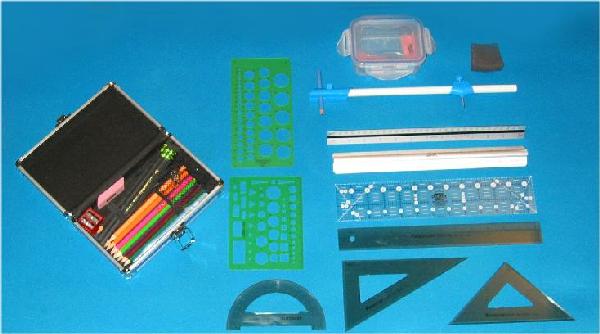
After the data points are collected, the data are usually plotted on some grid format to display a representation of the underwater objects being mapped. The plotting tools range from nothing more than a ruler and a compass to formal professional drafting tables and draftsman's tools. We carry drawing tools to the dive site in a flat cake pan carrier. These cake carriers can be found in the baking department of many department or arts/crafts stores. These particular containers are particularly convenient for carrying multiple light weight objects. They are easily stacked for storage. They are not water-proof. An example is shown below
 |
|
Cake Carrier Containing Drawing Tools |
Inside the cake carrier is a pencil box (holds a selection of colored pencils, a pack of "eco-pencils" (these are triangular shaped and quite comfortable to use ... ours are the Dixon "Tri-Conderoga" brand), a pencil sharpener, soft rubber eraser, and a compass). a "beam compass" (used for drawing large arcs), a black piece of hard foam to protect the rather sharp beam compass point, an architects scale, several rulers, a protractor, a couple of drawing templates, and a couple of drawing triangles. Quilt shops and fabric stores are convenient places to get rulers. (Rulers for fabric measurements tend to be very accurate and most start with the zero point on the exact end of the ruler.)
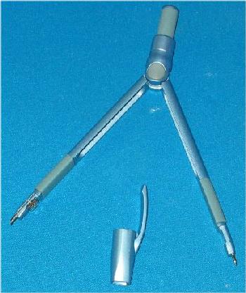
For storage, the beam compass is disassembled, the blue parts (pivot (with foam protecting the point) and pencil) are separately stored in a small lock-and-lock container and the plastic rod is simply placed into the cake carrier. This minimizes risk of damage to the compass, particularly the small pencil. Spare pencils can be stored in the small lock-and lock box.
 |
|
Drawing Tools |
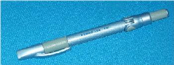
One particular device we particularly like is a "ball-point" compass (Staedtler #9582). The compass folds into a convenient ball-point pen shape which protects the device while covering the sharp point. The compass is shown below in closed (left) and open (right) positions.
 |
 |
| Closed | Open |
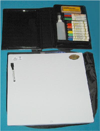
A dry-erase white board is a convenient briefing tool. Ours is a 17" x 17" magnetic white board with an Expo dry board writing kit (colored pens, cleaning fluid and dry eraser), below, left. This stuff conveniently fits into a large "teacher's tote," below right. We also use the large teacher's bag to carry large rolls of duct tape, a supply of underwater writing paper, charts, and other small items.
 |
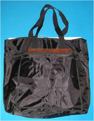 |
| Magnetic White Board | Board in Teacher's Tote |
The briefing is especially important in data collection. It is generally conceded that research divers should be focused on their mission and that operational parameters are best controlled on the surface. The more divers underwater must decide what to measure, the more hap-hazard the data collection. (In general, the less divers think underwater, the more productive the dive.) We typically operate our dives in a sketch and record repetitive cycle:
The first dive of a cycle is to sketch major features (to highlight potential targets to be measured) of the site to be surveyed. This also facilitates diver familiarization with the site and objects to be measured. These data are transferred to the white "mission board" and dive teams are assigned specific measurements to be made during the next dive.
After the diver's return from their measurement dive, their data are quickly placed on a grid to provide a crude image of measured objects. With this knowledge available, divers return to the site to sketch remaining targets (often completion of measurements started on a previous dive). This second sketch is used to plan the next measurement dive.
This cycle of sketch and measure is continued until the site is totally defined.
Although this sketch-measure cycle might appear a bit redundant, in the long-term it provides the most time-efficient use of in-water personnel because "what to measure" decisions are always made according to a surface-planned scheme that is based on previously accumulated data.
Gathered data and measurements from each dive are transferred using the trilateration data, sketches and the above drawing tools to a grid system that will ultimately define the surveyed area. This can be any size or or scale graphing paper. Typically, this is 1/4" or 1/10" squares on either 8 1/2" x 11" (individual) or 26" x 24" (group) size paper.
Conclusion
With a few simple tools, a lot of in-water time gathering data, and some tedious post-data gathering plotting, accurate representations of underwater objects can be obtained. Regardless of the sense of tedium that may sometimes overwhelm the diver while underwater, watching a chart emerge as data is plotted is a most welcome and wonderful feeling.
Acknowledgements
The data board was inspired from observations at a MAST course (Vermillion, Ohio) on Underwater Archeology
The author gratefully acknowledges MAST for allowing use of their data form template.
Thanks to Kim and Tom at Aquatic Adventures (Brighton MI) and Craig at Sea The World Diving (Farmington, MI) for technical assistance.
Jump To:
Video Camera Deployment Line Chest Harness Shore Baseline Underwater Baseline Markers Crate
Tie-Wrap Holder Measuring Stuff Plumb Bob Grids Data Board Entering Data Drawing Stuff
Go To: Home About "Harris" Articles Slides War Stories Editorials Links Fini
About
The Author:
Larry "Harris" Taylor, Ph.D. is a biochemist and Diving Safety Coordinator at the University of Michigan. He has authored more than 200 scuba related articles. His personal dive library (See Alert Diver, Mar/Apr, 1997, p. 54) is considered one of the best recreational sources of information In North America.
All rights reserved
Use of these articles for personal or organizational profit is specifically denied.
These articles may be used for not-for-profit diving education