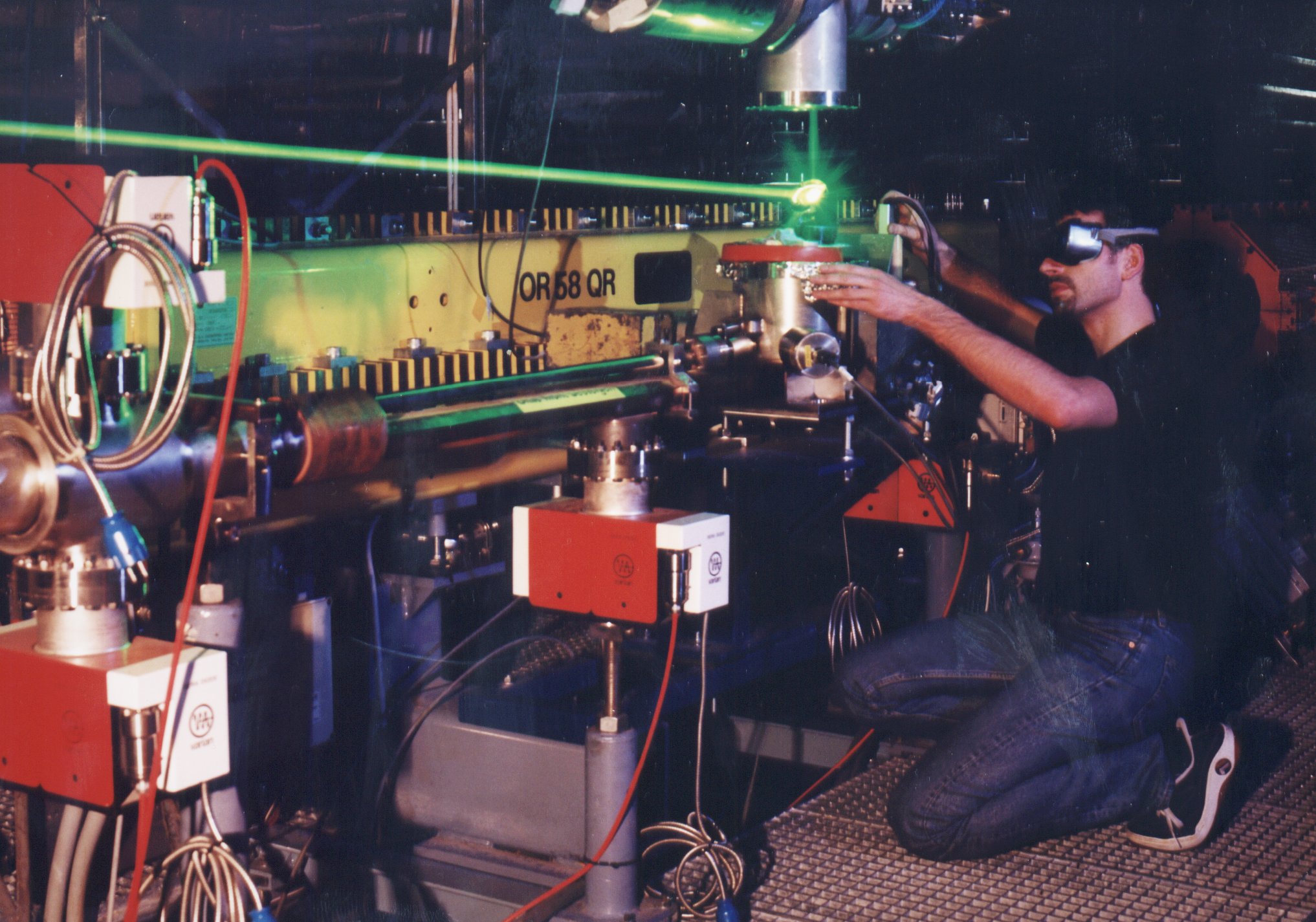
A few PR shots taken by the professional photographer Manfred Schulze-Alex, Hamburg. The copyright for these pictures belongs to DESY.
|
|
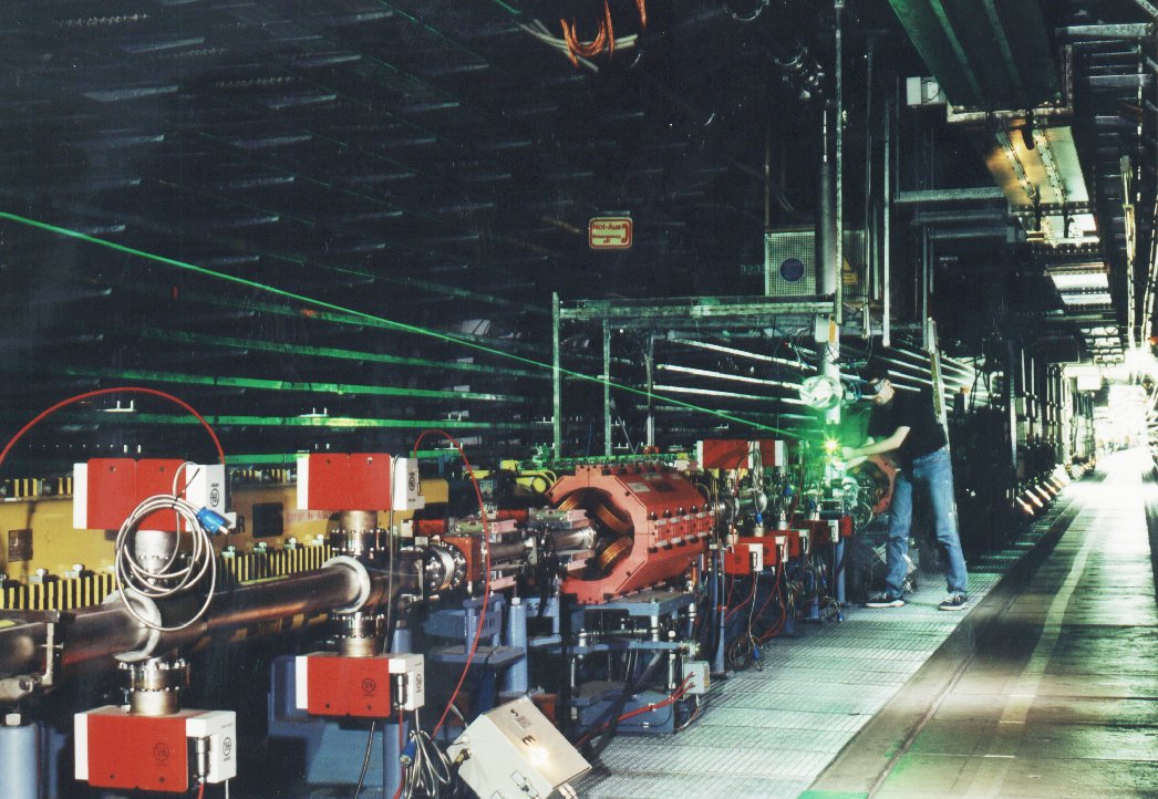
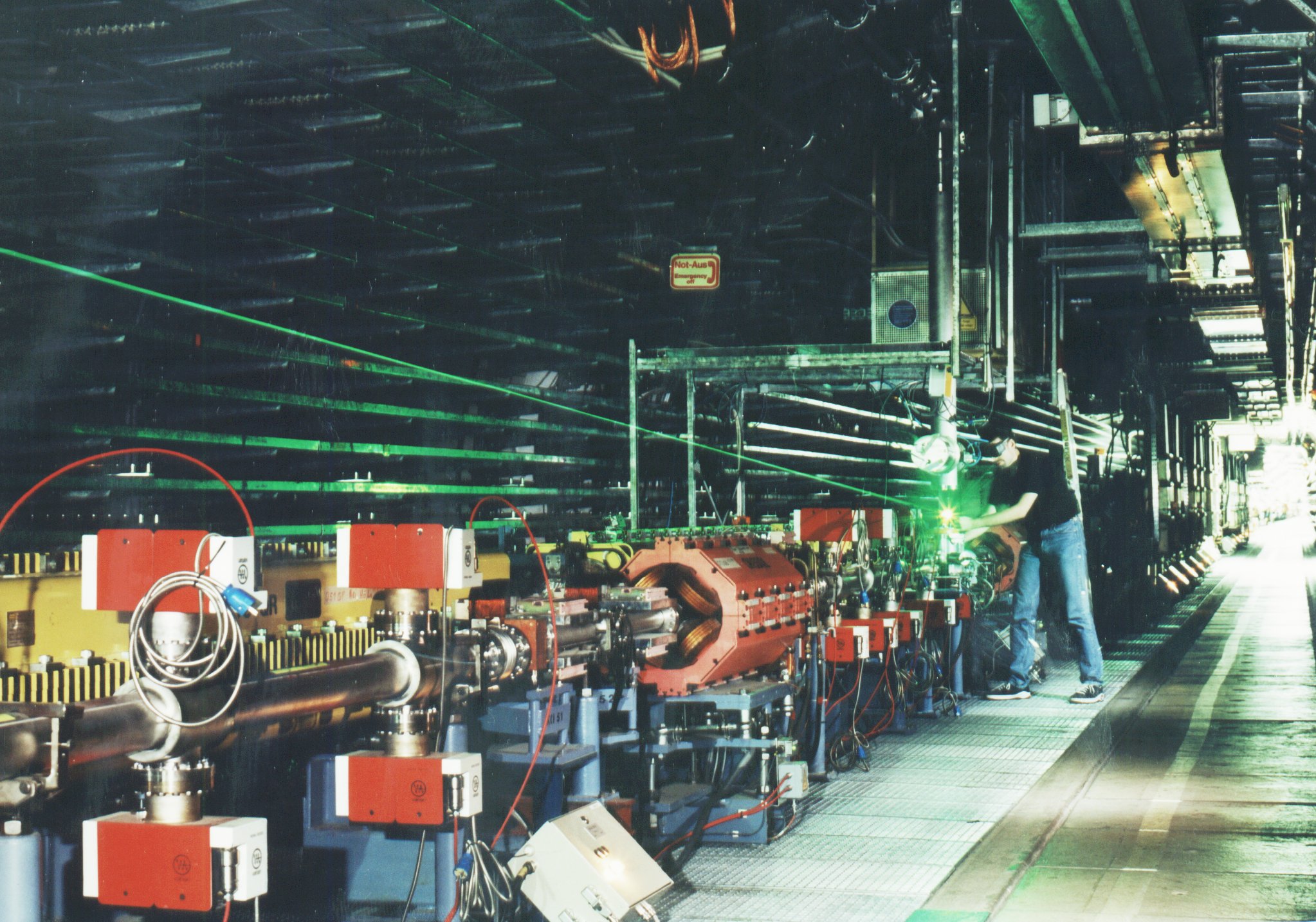
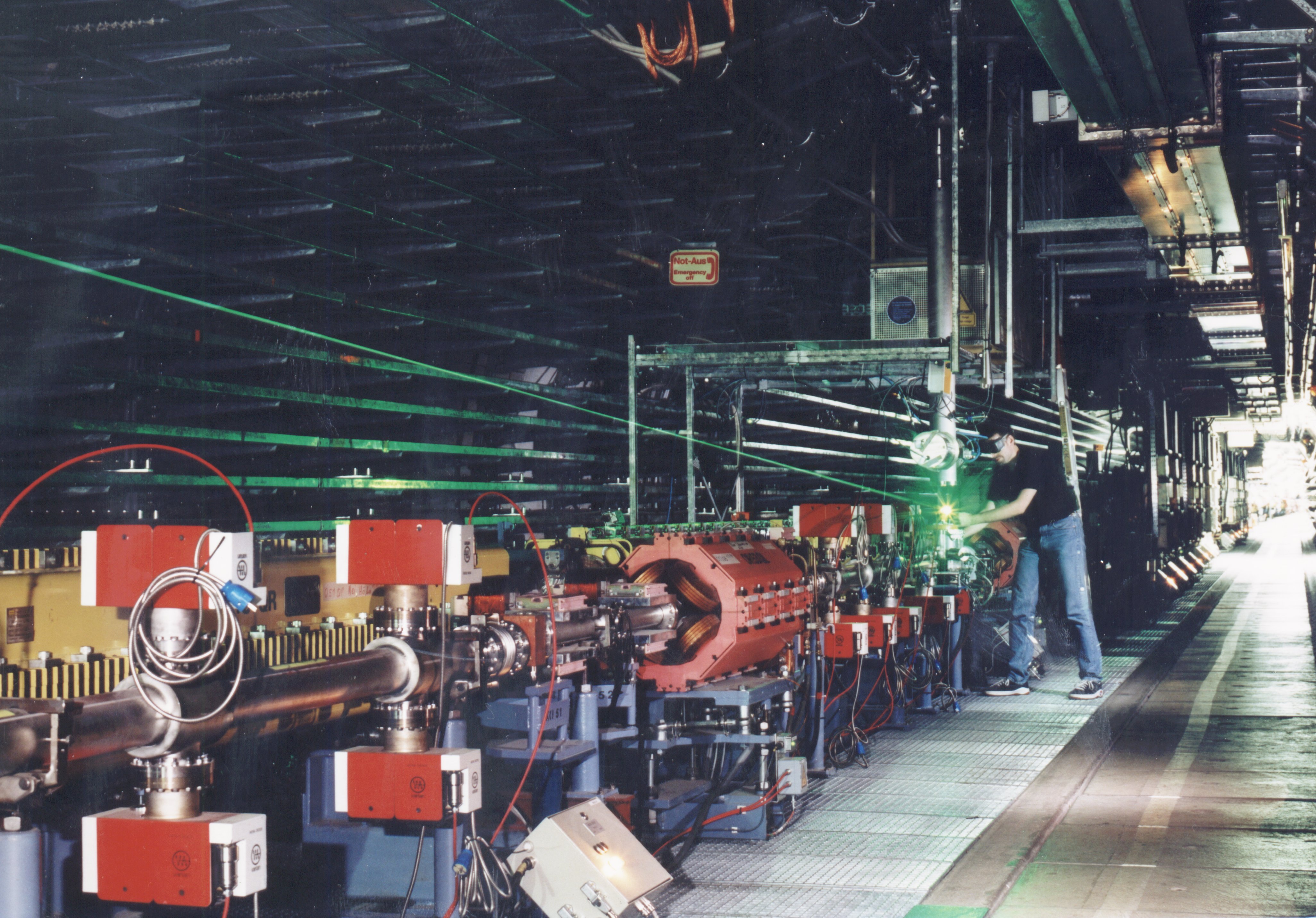
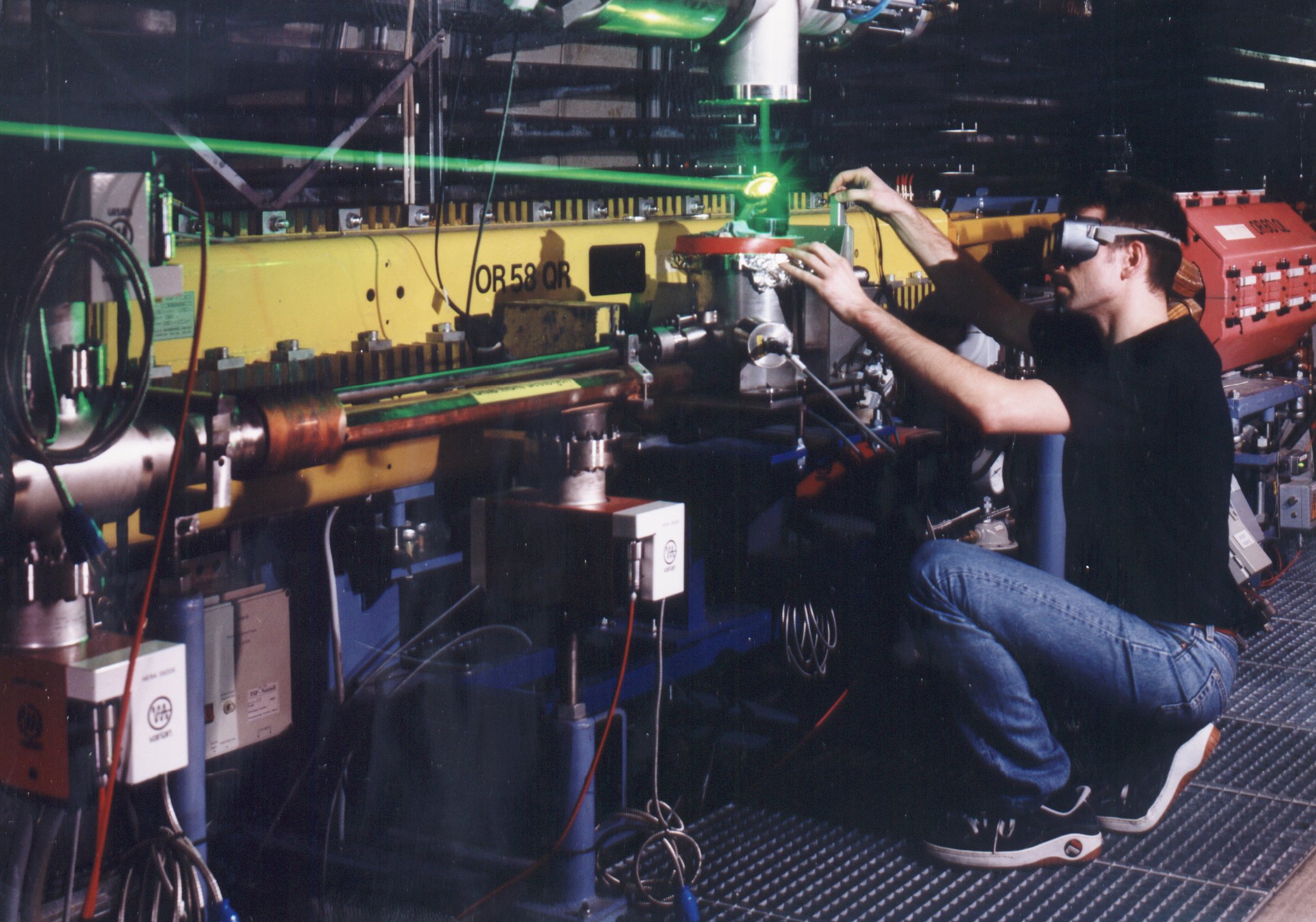
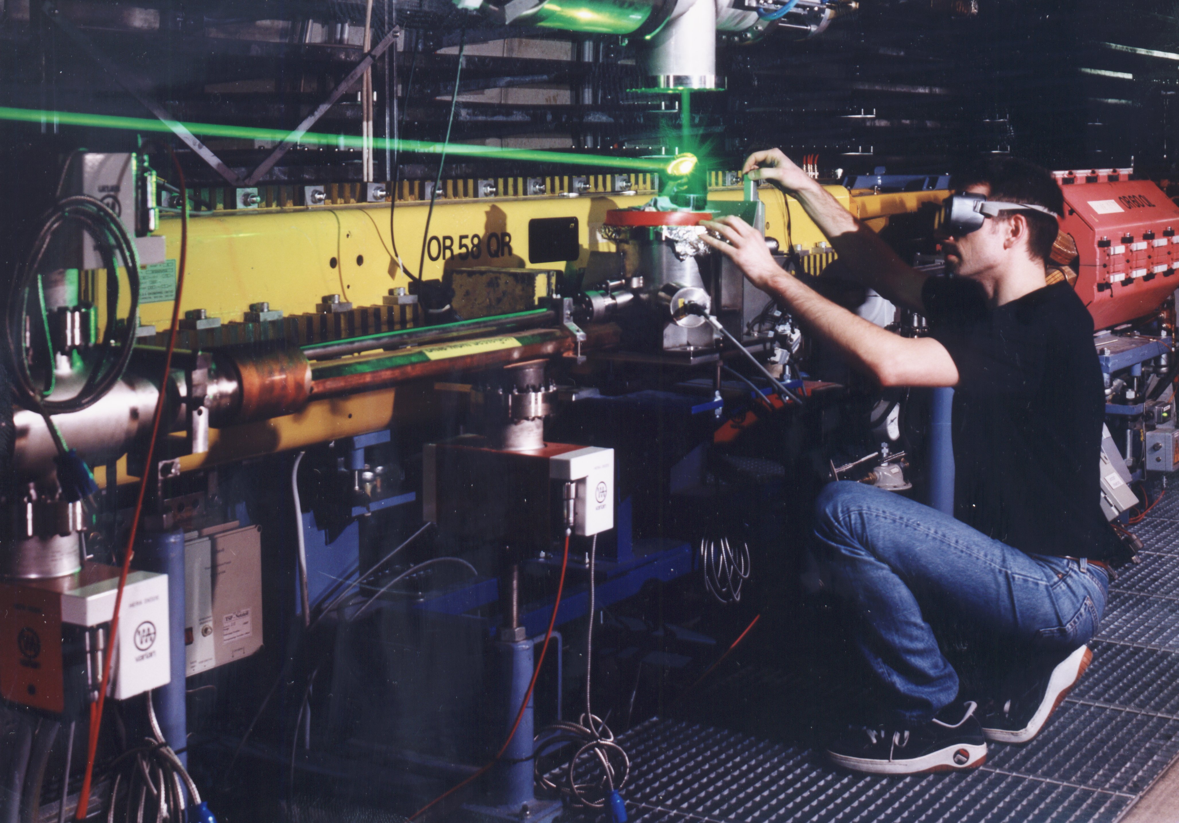
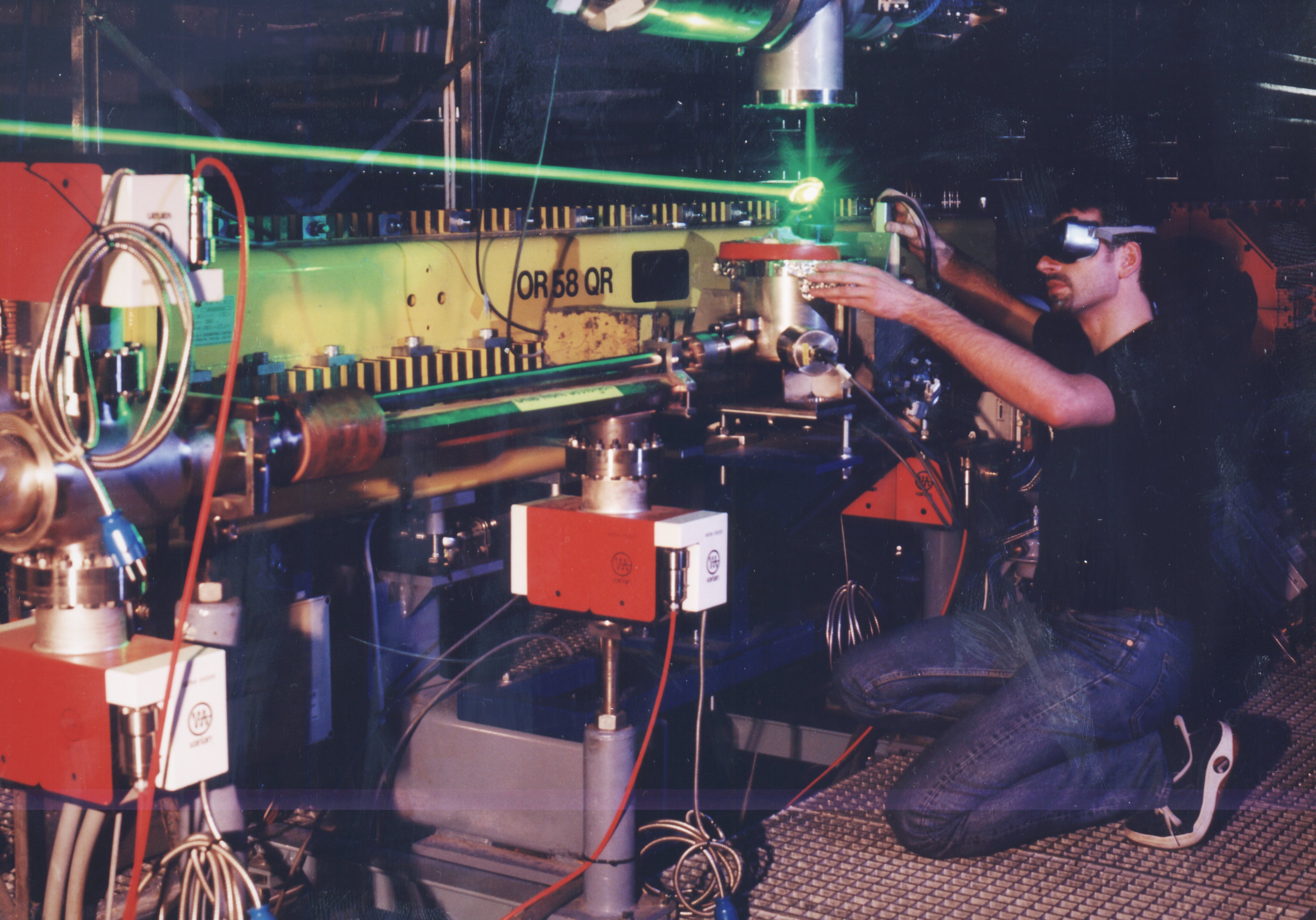
A view into the HERA tunnel with the laser beam guided above the HERA beam line for adjustment. |
|
|
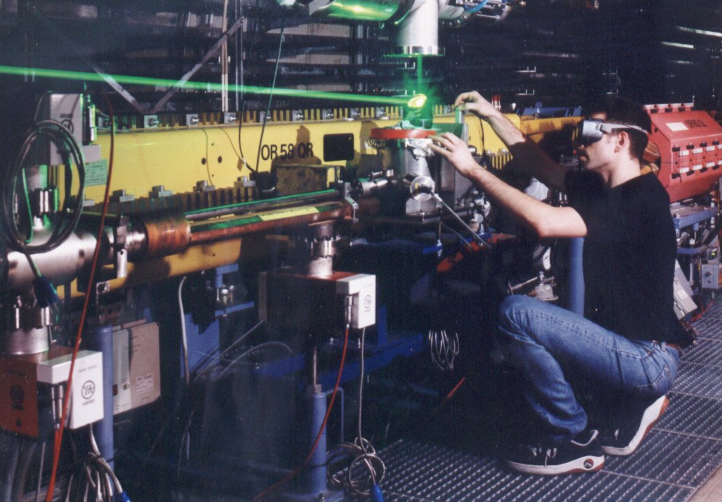
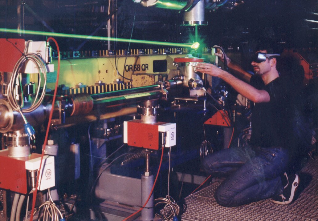
A closer look at the location of mirrors M5/6. |
|
|
Another close look at the location of mirrors M5/6 with slightly different illumination. |
Click on the small pictures to see them in full size.
|
A view of the Pockels cell and other optical components in the laser hut. The laser beam is coming from the right, deflected by the two "dog leg" mirrors, passing through the Pockels cell and the beam expander into the entrance of the laser transport system, visible in the upper left. |
|
The beam expander, looking against the direction of the laser beam. |
|
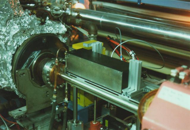
The crystal calorimeter in the HERA tunnel at OR 107, mounted on the moveable table. In the left you can see parts of the last cavity behind which the Compton exit window is mounted. The pipe running from the middle left to the bottom right in the foreground is the HERA electron beam pipe, the proton beam pipe is visible behind the calorimeter. |
|
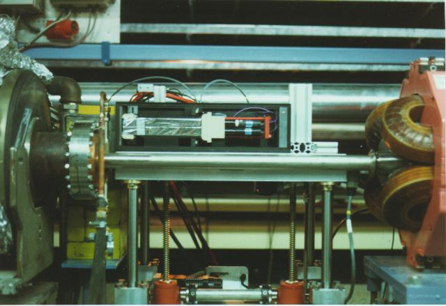
The opened crystal calorimeter in the HERA tunnel, mounted on the moveable table, viewed from the side. You can see the wrapped crystals in the left and the photomultipliers to the right. The pipe running in front of the table underneath the crystals is the HERA electron beam pipe. To the left of the calorimeter, the flange holding the Compton photon exit window is visible. |
|
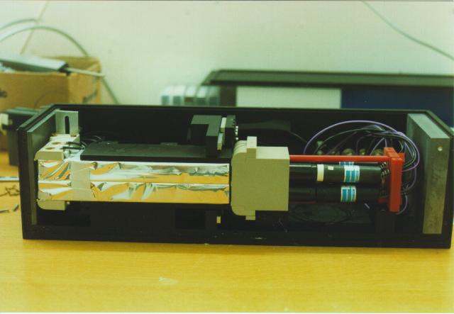
The crystal calorimeter with the cover removed on a bench. In the left two of the four crystals, wrapped in aluminized mylar foil, are visible. The block continuing to the right of the crystals holds the four PMT tubes, two of which can be seen extending from the mounting block into their bases. A nickel foil can be moved in between the crystals and the mounting block. |
|
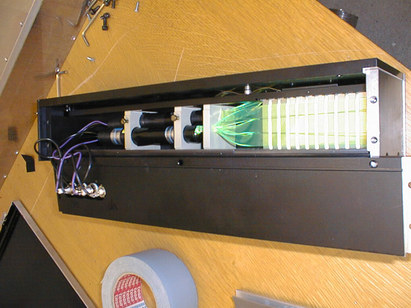
A full view of the sampling calorimeter with the side plate opened. To the far right, the Tungsten absorber plate. Proceeding to the left, alternating Tungsten and Scintillator material slabs. Wavelength shifters are situated just behind the last Tungsten slab and proceed on to the Photo Multiplier Tubes at the far left. |
|
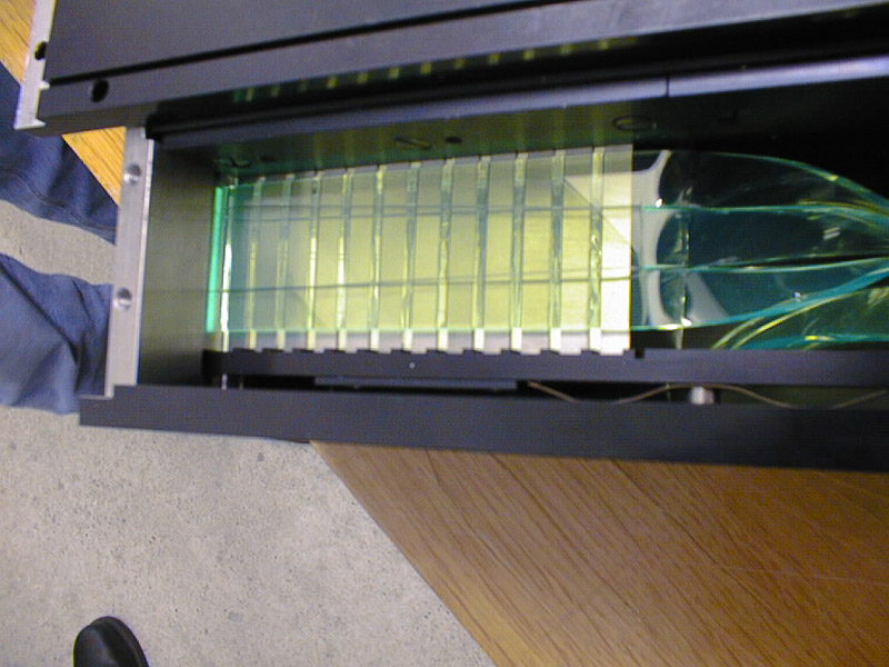
The sampling calorimeter and a closer look at the Tungsten/Scintillator slabs. The wavelength shifters can be seen to the right. |
|
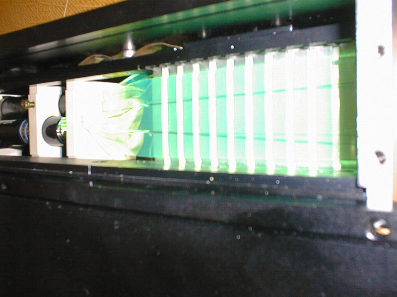
The sampling calorimeter being lit by scintillation light. |
Last modified January 10, 2005