|
A view of the Pockels cell
and other optical components in the laser hut. The laser beam is
coming from the right, deflected by the two "dog leg" mirrors, passing
through the Pockels cell and the
beam expander into the entrance
of the laser transport system, visible in the upper left.
|
|
The beam expander, looking
against the direction of the laser beam.
|
|
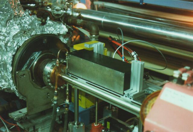
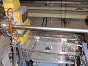
The crystal calorimeter in the
HERA tunnel at OR 107, mounted on the moveable table. In the left you can
see parts of the last cavity behind which the Compton exit window is mounted.
The pipe running from the middle left to the bottom right in the foreground
is the HERA electron beam pipe, the proton beam pipe is visible behind the
calorimeter.
|
|
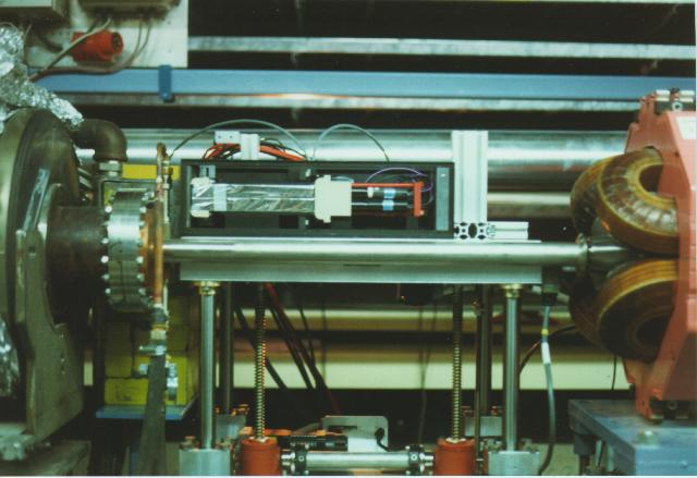
The opened crystal calorimeter in
the HERA tunnel, mounted on the moveable table, viewed from the side.
You can see the wrapped crystals in the left and the photomultipliers to
the right. The pipe running in front of the table underneath the
crystals is the HERA electron beam pipe. To the left of the
calorimeter, the flange holding the Compton photon exit window is visible.
|
|
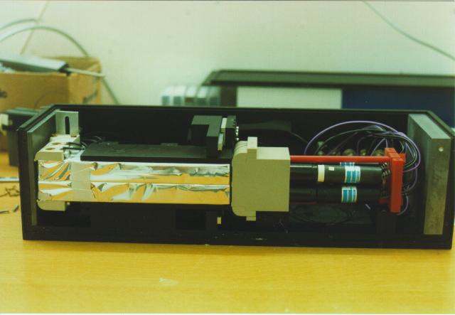
The crystal calorimeter with the
cover removed on a bench. In the left two of the four crystals, wrapped
in aluminized mylar foil, are visible. The block continuing to the right
of the crystals holds the four PMT tubes, two of which can be seen
extending from the mounting block into their bases. A nickel foil can be
moved in between the crystals and the mounting block.
|
|
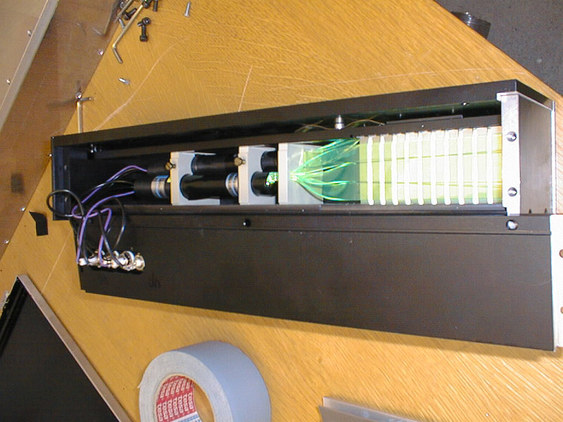
A full view of the sampling calorimeter with the side plate opened. To the far right, the Tungsten absorber plate. Proceeding to the left, alternating Tungsten and Scintillator material slabs. Wavelength shifters are situated just behind the last Tungsten slab and proceed on to the Photo Multiplier Tubes at the far left.
|

|
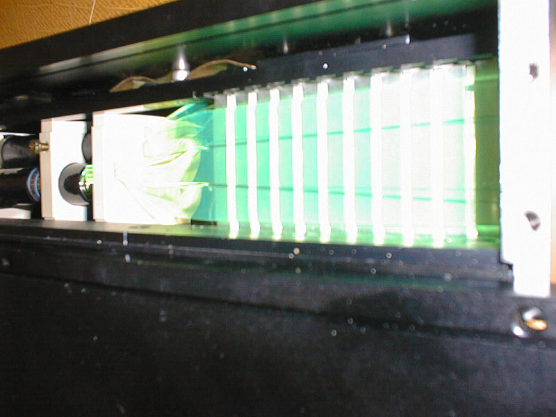
The sampling calorimeter and a closer look at the Tungsten/Scintillator slabs. The wavelength shifters can be seen to the right.
|
|
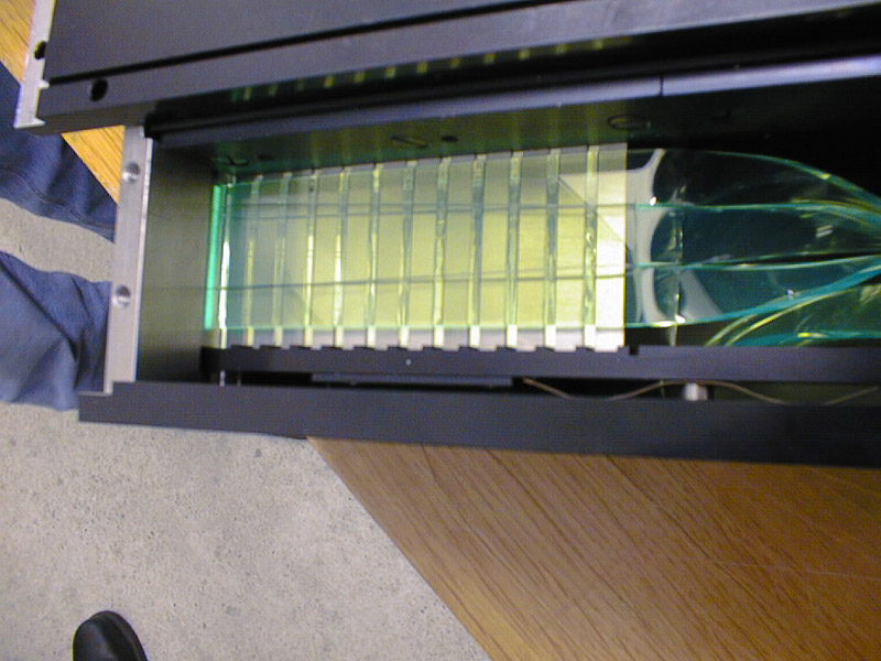
The sampling calorimeter being lit by scintillation light.
|
Learn from pictures about LPOL hardware:
|
The calorimeter is mounted on a table which can be moved remotely in
horizontal and vertical direction.
|
|
A pair lenses located in from to mirror 4 is used to focus the laser beam
onto the electron beam at the position of the IP.
|
|
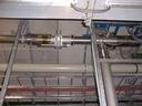
A pair of mirrors (5/6) are used to guide the laser beam into the electron
beam line. The laser beam vacuum is physically separated from the electron beam
vacuum by a window.
|
|
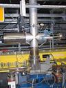
The mirrors 5/6 are mounted together on a single rod that can be moved in
horizontal and vertical direction in the vacuum through a bellow. Therefore
the mirrors 5 and 6 are always moved together.
|
|
Mirrors in a vacuum system are used to guide the laser beam from the laser hut
in the 6th floor down to the interaction point (IP). The mirrors 1 to 4 are
phase matched with a diameter of 4 inch. The mirrors 5 to 8 are smaller with
a diameter of 2 inch.
|
|
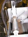
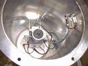
The camera box is an aluminum cylinder containing a CCD camera that is focused
onto a exit window of the laser vacuum system right behind a mirror. Attached
to the exit window on the outside is a piece of paper with a grid in millimeter
spacing to help calibrate the location of the laser beam spot. The box is
connected to the laser interlock system. A light source is mounted behind the
camera to deliver indirect light onto the paper.
|
|
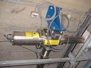
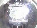
Mirrors 1 to 4 are mounted in the vacuum using an identical holding
mechanism which is equipped with two stepping motors. This allows the
mirror to be moved in order to change the laser light position
vertically and horizontally downstream of the mirror.
|