

| |
| Home |
| About |
| News |
| Subsystems |
| Photos |
| Links |
| Contact |
| MCubed Blog |
| Michigan Space Blog |
| S3FL |
| High Altitude Solutions |
| SUBSYSTEMS | ||||||||||||||
Please use the navigational links to guide you through our subsystems. Satellite Description Satellite DescriptionM-Cubed is flying a CMOS camera in order to fulfill the objective of taking a better than 200 meter-per-pixel color picture, the highest resolution image taken on the cubesat platform. It will be powered by a battery that is charged by solar arrays on the outside of the structure. A microcontroller will process and send the image to the telemetry system for transmittal to ground, and the ground station will receive the picture over a period of time. The orbit of the satellite will be controlled by a passive attitude control system and will be oriented based on the Earth’s magnetic field. The structure has specified requirements from Cal Poly for launch vehicle integration, but will be designed such that M-Cubed will meet its mission objective. The following table details the requirements specified by Cal Poly for the cubesat platform The following table details the structural requirements specified by Cal Poly for the cubesat platform
A payload has been chosen such that it will fulfill the mission objective and provide color images of Earth in the visual spectrum with a size of at least one megapixel, at a ground resolution of better than 200 meters per pixel. To achieve this, the payload subsystem will consist of a CMOS camera and a plano-convex lens, with focal length designed to provide the required resolution. CameraThe chosen camera is a IDS-UI-1646LE-C Color CMOS Camera. The progressive scan CMOS has 4.4 micron square pixels in a 1280 by 1024 array, which allows for a two megapixel image at full resolution. The data format is 8 bits per pixel, making each image two megabytes. Using JPEG compression algorithms, this data will then be compressed on-board before transmission by a factor of around 10. This will minimize transmission time while preserving visual quality of the image.
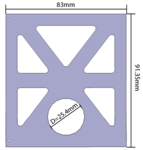
OpticsThe plano-convex lens will be rigidly mounted inside of the cubesat, as close to the wall as possible to allow for maximum focal length. The diameter will be 25.4 millimeters (mm), while other geometrical attributes will be designed to satisfy structural constraints and resolution requirements. With a worst case scenario maximum altitude of 800 kilometers (km), a focal length of at least 9.6 mm is necessary to achieve the desired ground resolution. The structure, however, may allow for a focal length approaching 60 mm, which allows for a ground resolution of better than 60 m per pixel, far exceeding the requirements. Shutter SystemDuring the initial tumble, and potentially other periods during orbit, the aperture may be pointed directly into the sun. Prolonged exposure to the sun may damage the CMOS and jeopardize the mission. Necessary precaution is being taken with the design of the optical system. If further analysis deems protection of the detector necessary, a small motorized shutter will be placed between the lens and the focal plane. The on-board controller will obtain sun vector data from solar panels, and determine when the shutter should be open or closed. This system will not be used as an operational shutter (used to limit exposure time), but rather used as an emergency protection device for the detector. Processing and Analysis To lessen the workload of the microcontroller, a Blackfin ADSP-BF561 Processor will be use solely to compress and process pictures.
Thermal Vacuum IIn order to space qualify all our CubeSat, a thermal vacuum chamber is used to test each component in a "space" evironment.
The orbits and controls subsystem team has two key objectives: to characterize the implications of the expected orbital trajectory, and to provide the cubesat with the proper attitude to facilitate Earth imaging. OrbitSince each group of cubesats is typically launched as a secondary payload, its precise orbital trajectory is dictated by the requirements of the primary mission. However, basic historical trends can be observed between each significant cubesat launch, which can be used to establish an approximate “reference orbit” to aid in mission design.
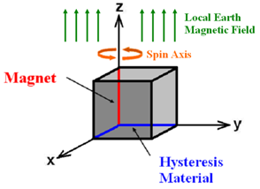
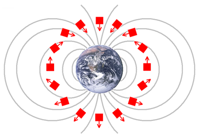
Passive Attitude ControlM-Cubed utilizes a passive magnetic attitude control system to achieve a proper orientation for Earth-imaging. The system consists of a single permanent magnet aligned on one cubesat body axis, along with additional magnetic hysteresis materials aligned on each additional perpendicular body axis. In this configuration, the permanent magnet aligns one body axis of the cubesat with the local Earth magnetic field direction. Since the magnet still permits cubesat rotation about this single axis, the hysteresis materials are added to dampen unwanted rotation. Chosen for their high magnetic permeability, the HuMy80 hysteresis materials create internal current as they are rotated through the local magnetic field. This dissipates rotational energy as heat, effectively damping the rotational motion of the cubesat. If each magnetic component of the passive attitude system is properly sized, a controlled spin rate can be achieved about the local magnetic field direction.
In practice, this passive attitude control system will allow for Earth-imaging throughout only a designated portion of the M-Cubed orbit. Ideally, the camera will continuously point in the nadir direction or straight down towards Earth. Since the camera is aligned along the permanent magnet axis, however, its direction relative to nadir is dictated by the cubesat’s orbital position.
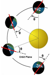
Due to this Earth magnetic field configuration, the passive magnetic control system will allow for ground coverage over a significant portion of the Northern Hemisphere. As M-Cubed passes over the North Pole, the permanent magnet and camera will be aligned in the nadir direction, due to the vertical direction of the local Earth magnetic field. As the M-Cubed orbit continues toward the Southern Hemisphere, the camera-nadir angle will increase until the Earth leaves the camera field of view. The Earth will then reenter the camera field of view after M-Cubed crosses the equator into the Northern Hemisphere. On average, this control strategy will allow for approximately 15 picture opportunities of the Northern Hemisphere per day (once per each 90 minute orbit). Although the Northern Hemisphere will remain in the camera field of view for approximately 40 minutes during each overpass, the window of opportunity will vary depending on ground lighting conditions. Although limited in performance, this type of passive control system was chosen for several reasons. When compared with active attitude control systems, such as magnetic torque coils, passive systems of this type require less mass and no power consumption. Furthermore, passive attitude systems offer a robust, simple control strategy that boasts extensive flight heritage in similar Earth-imaging cubesat missions. Orbital Simulators With the use of computer simulators such as Satellite Tool Kit (STK), we have been able to test orbital calculations and design an accurate additude control system.
IDuring the Fall 2008 semester, University of Michigan Aerospace Students constructed a Helmholtz Cage that can simulate Earth's magnetic field.
Magnet Details Magnet Torque Compared to Disturbance Torque
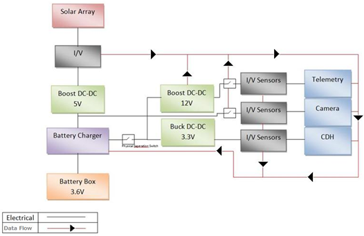
The main purpose of the power and electrical subsystem is to distribute adequate power to all of the subsystems. To accomplish this, M-Cubed utilizes both a battery and solar arrays placed on every side of the cubesat. The power collected by the solar cells is sent through current and voltage sensors connected to the microcontroller and then through a 5 Volt (V) voltage converter, where is it dispersed between active buses controlled by switches (during Discharge Mode) or to the battery charger (during Charge Mode). When M-Cubed is in Discharge Mode, the solar cell power is supplemented by the battery power through either a 3.3 V or 12 V voltage converter to power other buses. In Charge Mode, the microcontroller opens all switches to remove power from all other subsystems and directs all solar power through the battery charger. The entire satellite is expected to require 1.2 Watts (W) of average power and 4.7 W of peak power.
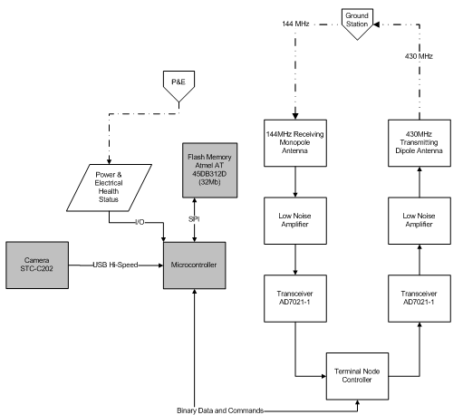
The power and electrical subsystem has to accommodate a variety of power needs. While M-Cubed is in eclipse, all components will be in low-power or standby mode. If the cubesat is in sunlight and takes a picture, the shutter, camera, and microcontroller will all need full power to operate. After a useable picture is taken, the cubesat will wait again in low-power mode until it enters the ground station coverage area at which point the transmitter will be switched to full power mode. A versatile power system requiring the use of a rechargeable battery system is necessary to accomplish these tasks. Solar ArraysSolar arrays cover each side of M-Cubed and send power through the main circuit board to be sent to various components on the satellite in 3.3 V, 5 V and 12 V power-buses. On the way to the main circuit board, the power is passed through a charging circuit, where the power is either stored in the battery during the charging phase or, if necessary, supplemented with power from the battery. These arrays are also used by the orbits and controls subsystem to create a sun direction vector used to calculate spacecraft orientation. BatteryIn addition to solar arrays, M-Cubed receives power from four small Polymer Li-ION batteries onboard. These batteries each have a capacity of 3.89 Watt-hours (W-h) and were chosen over a larger battery due to their higher discharge rate and energy density. The cubesat requires a battery for the mission because the solar cells alone cannot produce enough power when peak power is needed. The battery also provides power to subsystems that cannot be turned off while M-Cubed is in eclipse. Although we anticipate M-Cubed to have a sun-synchronous orbit, there is a chance that M-Cubed is launched into an orbit with an eclipse period. The battery has been the primary driver of the thermal subsystem due to the small range of temperatures in which the battery can operate. The telemetry subsystem’s main objective is to transmit the data from onboard M-Cubed to the ground station. Using a 144 MHz uplink and a 437 MHz downlink, amateur radio bands will be used to control and receive data from the satellite. A basic beacon signal containing satellite health data will be transmitted intermittently throughout operations. Data and commands will be transmitted using the AX.25 protocol [1], a standard in amateur radio data transmission. This protocol is often a failure point for other picosatellites, therefore the system will utilize an existing software implementation for reliability. Onboard CommunicationsA dedicated receiver will operate at all times, while the dedicated transmitter will be operated only to send a beacon signal or transmit picture data. Both receiver and transmitter are the same component, Analog Devices ADF7020-1 [7], hardwired to their independent tasks to save development time and costs. From the transmitter, the signal will be amplified to 1 W, the calculated necessary transmit power. A 0.33-m dipole and a 0.5-m monopole are the respective antennas for uplink and downlink. Significantly more analysis and design will be dedicated to this part of the subsystem. Ground StationThe ground station will be able to autonomously receive data from M-Cubed throughout the day, reducing the human oversight required. S3FL is working closely with the University of Michigan Amateur Radio Club (ARC) on this task. The ARC has expressed great interest in sharing resources with other student groups such as S3FL and has a declaration of intent to expand its space communication capabilities. The ARC’s facilities will be utilized for the duration of the mission and include a dedicated ground computer, IC-910H transmitter, a tracking 13.1 dBi circularly polarized Yagi antenna, preamps, and supporting cabling. This equipment will be adequate for M-Cubed’s purposes and prevent further expenses. Command and Data Handling
ComputerThe I2C interface will connect to an EEPROM containing program memory while SPI will connect to a flash device storing data memory, and the UART interfaces will connect to the telemetry system. SoftwareAnother driving factor in the selection of a microcontroller was ease of programming and scalability. The Atmel AVR32 7002 microcontroller is capable of running a Linux operating system. To control the camera and compress the images along with the implementation of the AX.25 protocol, the software will use open source code which has already been thoroughly tested, decreasing development time and increasing reliability. An additional benefit is the scalability of the microcontroller processing, thus providing a flexible platform for future cubesats. To design the structure, several criteria were set. First, the structure must comply with all requirements. Secondly, the structure needs to provide a proper vessel for the primary payload, the camera, to operate unobstructed. The structure was designed to minimize mass while maintaining structural strength capable of withstanding the greatest possible launch loads, which is currently the DNEPR vessel [4] with loads up to 10 G’s. Finally, a structure was designed that can be accessed with ease by the different subsystems. This would provide a platform that would facilitate testing and if needed, changes to the components.
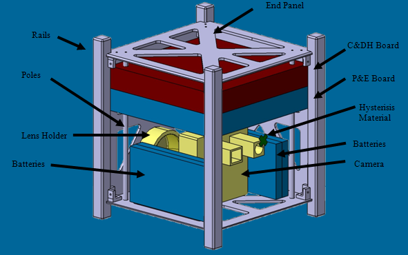
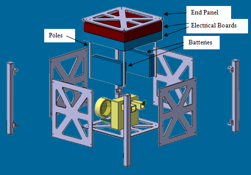
AssemblyThe main structure is composed of six rectangular isogrid panels attached to four rails at each corner. The isogrid panels provide rigidity while being lower in mass than a solid panel. This reduction in mass allows for thicker panels that become a better medium through which necessary holes can be drilled. All panels, minus the bottom, contain similar patterns. The bottom panel is modified to provide a circular opening for the camera lens. The rails to which these panels are attached will be hollowed out from the bottom face to reduce mass as well as providing a channel through which the power and electrical subsystem can access the spring-loaded plunger necessary to indicate M-Cubed’s release from the P-POD (Poly Picosatellite Orbital Deployer).
Payload Support SystemThe payload support system consists of 4 cylindrical poles screwed into both end panels. These poles will be used to slide both C&DH and power and electrical boards into the structure and will be secured using stoppers. The battery will also be attached to the poles by a compatible casing developed by the structures subsystem. This support system can then be accessed by unscrewing the poles from one panel and detaching the opposite end panel, bringing with it the poles and all the components secured to it.
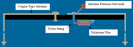
Antenna DeploymentM-Cubed requires a deployment mechanism for both antennas needed for communication with the ground station. The 130 MHz receiving antenna is a 0.33-m long dipole while the 435 MHz transmitting antenna is a 0.5-m long monopole. Both antennas are made of copper tape shaped to maintain a straight profile. The monopole antenna is fastened at one end while the dipole is fastened at its midpoint. Both antennas will be wrapped around the structure perpendicular to each other. The remaining ends are then tied down to the inside of the structure using nylon string with nichrome wire wrapped around it. When the antennas need to be deployed, a current will run through the nichrome wire, melting the nylon string and allowing for the antennas to release to their straight unfurled position.
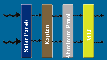
ThermalTo provide proper protection from radiation and heat fluxes, a passive thermal protection system consisting of proper insulation has been proposed. This insulation will consist of a layer of Kapton outside the panels, which will also act as an adhesive for the solar panels, and MLI inside the structure. Since solar panels will be covering most of the panels, the layer will be acting as additional insulation. Additional thermal covering will be used around the batteries, which are the most thermally sensitive components. A rendering of the insulation is shown below in Fig G.1.
|
||||||||||||||


|