Building the Charger 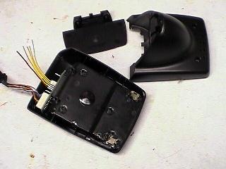 Here's the inside of the Qualcomm charger. The power supply has been removed and you can see the wires have been cut. This stuff will go in the trash. If you trace the wires out, the red wire is negative (ground) and the far opposite yellow wire is used to power the interface circuit on the connector board. Only the red wire and the middle yellow wires connect to the battery connector pins. Further tracing the wires into the battery pack, the red wire connects to the protection board negative, the first yellow wire connects to a thermistor on the ribbon board, the second yellow connects to a resistor on the ribbon board and the third yellow wire connects to the protection board positive. The other end of the thermistor and resistor connect to the red wire. 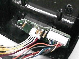
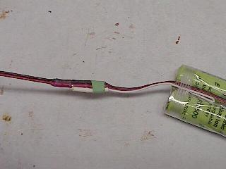
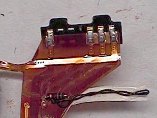 Here's where I traced out the wire to find out where they go. So at this point we need to scavenge the thermistor and resistor off of the ribbon board. While we at it, unsolder the ribbon board and the the center tap strap from the protection board. Then set this stuff a side and well mount the power supply board. If you use the same box that I did, you'll need to shave some plastic channels off the inside of the box to get the power supply circuit board to fit. Mount the power supply board to the lid of the box using standoffs. You'll need to make three holes in the lid for the screws and one for the LED. Next cut a notch in the box to slip the power cord strain relief into. Finally cut a notch in the lip of the lid for the output cable. 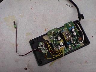 Parts mounting. Make up another servo wire cable just like the one for the battery - only reverse the sexes of the pins for each wire (e.g. black is female, red and white are male). Solder the other end of this cable to the battery connections on the protection board scavenged from the battery. Next solder one lead of the scavenged thermistor and resistor to the available foil pad next to the negative charger connection. Now attach the red and yellow wires from the power supply board as follows. Connect the red wire to the negative charger connection pad on the protection board - this is closest to the black wire to the battery. Connect the first yellow wire to the free lead of the thermistor - put a piece of heatshrink over this connection. Connect the second yellow wire to the free lead of the resisor. Connect the third yellow wire to the positive charger pad on the protection board - the one closest to the red battery cable contact. You can put a piece of tape onthe remaining yellow wire - it isn't used. Finally mount the protection board to the lid of the box using a piece of servo tape and close up the box. 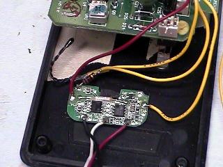 Hooking up the protection board. Now connect the battery to the charger (the leads below are not pushed in all the way so you can see the pins mating. Plug the charger in and the LED will go red to indicate charging. When the battery is charged, the LED will go green. If you unplug the battery while power is on the charger, the LED will begin flashing red and you have to unplug the charger to get it to stop - plugging the battery back in won't do it. I found that you could put a switch in the positive lead from the power supply board to the protection board to get around this problem, but I didn't think it was worth it. Once the battery is charged, I just plug the lead from the ESC into it the black and red connections - the white wire just comes along for the ride. 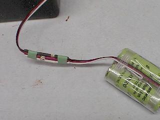
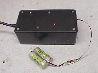
 Hooking up the battery to the charger and the plane. I've also used this charger on a couple of the Goldmine batteries. They take longer to charge but other than that there were no issues in using the charger on them. Update (12/28/2001): After further discussions and suggestions on the e-Zone, I decided to relocate the thermistor. I've added a holder to the top of the box (between the LED and the edge of the box. I mounted a thermistor from a disected pack inside of the holder so that it is pressed tightly against the pack. The holder is an end cap from an old 6-cell car pack. It's slightly larger than the Li-Ion pack so I lined the inside with a layer of foam wing seating tape so the the battery pack is a tight fit. 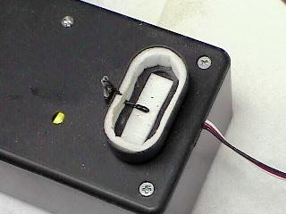 The holder with thermistor installed. Those are my mods. Take them for what it's worth. Now the caviats and disclaimers. First, the thermistor was probably installed in the pack to indicate an over temp condition to the charger - since the thermistor is relocated to the inside of the charger, it doesn't have a clue what temperature the battery is at. The change to locate the thermistor in the holder helps, but is still not perfect. In either case, I don't think this is a problem, but I don't have enough experience with it to know. Second, removing the protection board from the pack removes the over-current and under-voltage protection. If you over load the cells or discharge them below their lower limit, they're going to die - with the over current condition, this may be a violent death with associated self incineration. Third, do I need to mention that this is completely outside of the manufacturer's intended use for the charger and battery. And you'll void the warrenty. Fourth, this worked for me. I'm offering the information with no promises of guarantees. Use it at your own risk. Finally, if you have any more information about the inner workings of the circuits involved, please feel free to contact me. Update (01/14/2001): I've had a couple of email exchanges about the indicator flashing red instead of coming on solid. This seems to be a problem with the battery pack and in all cases so far, the problem has been correctable. The LED on the charger indicates three things depending on what it's doing. Green indicates charged, Red indicates charging, and Flashing Red indicates a fault condition in the battery. Briefly, when you first connect a battery, the LED should come on green and then change to red. It will stay red during the charge and trun to green when the pack is fully charged. If the charger discovers a fault condition, the LED flashes red. The fault conditions I've identified are under voltage, over temp, and failure to reach full charge in a set length of time. It may also detect over voltage, but I haven't tested this. The instances I have seen (and corresponded on) have been initial under voltage on the pack. I had one pack that initially read about 4.8 volts with both cells reading about equal. The correspondents had packs with one cell reading above 3 volts and the other reading way below. What has worked is to manually charge the low cell to 3 volts using a regular charger. In my case I used an Astro 110 set to 0.3 amps. My initially bad pack has a half dozen cycles on it and I see no performance difference between it and three other packs that did not have this problem. If you get a red flashing light, first determine that the pack is indeed low. If this is the case, measure each cell and determine if they are at the nearly the same voltage. If they are, ou can charger the whole pack, if one is higher than three volts and the other is low, charge only the low cell. Here is what I did with the Astro 110... 1) Set the charger current to minimum. 2) Put the pack into a coffee can - just to be safe. 3) Connect the battery or cell to the charger. 4) Advance the current to about 0.3 amps. 5) Monitor the terminal voltage and stop the charge when it reaches 3.1 volts for a single cell or 6.1 volts for the pack. 6) Remove the pack from the Astro and connect it to the Qualcomm charger to finish the charge. If the pack doesn't start coming up in a couple of minutes, it's probably best to write it off and pitch it. Also, if your charger doesn't have a voltage display, you'll need to connect a volt meter across the battery to monitor the voltage. If it doesn't come up to 3 volts per cell in 5 to 10 minutes or it still won't charge on the Qualcomm charger after this boost, pitch it. BIG WARNING: What ever you do, DO NOT leave the Astro charger to automatically terminate the charge. Lithium chargers work differently from peak detecting NiCd/NiMH chargers. Peak detecting chargers are only constant current chargers - they terminate by detecting the drop in battery terminal voltage that occurs when the battery reaches full charge. Lithium chargers operate constant current until the battery reaches its full terminal voltage, then the charger switches to constant voltage output and the charge current falls as the battery reaches full charge. "Full charge" for a Lithium battery is defines as the charge current falling to a specific level. If you leave the pack on a peak detecting charger, the charger will keep pumping full current into the pack until it fails catastrophically!. |
© 2001 A. Roger Wilfong